
It's not everyday I get tasked with creating a piece of electromechanical bondage furniture, such an unusual project I couldn't resist the challenge, and it's perhaps my most eccentric creation yet!
Bondage Furniture Plans
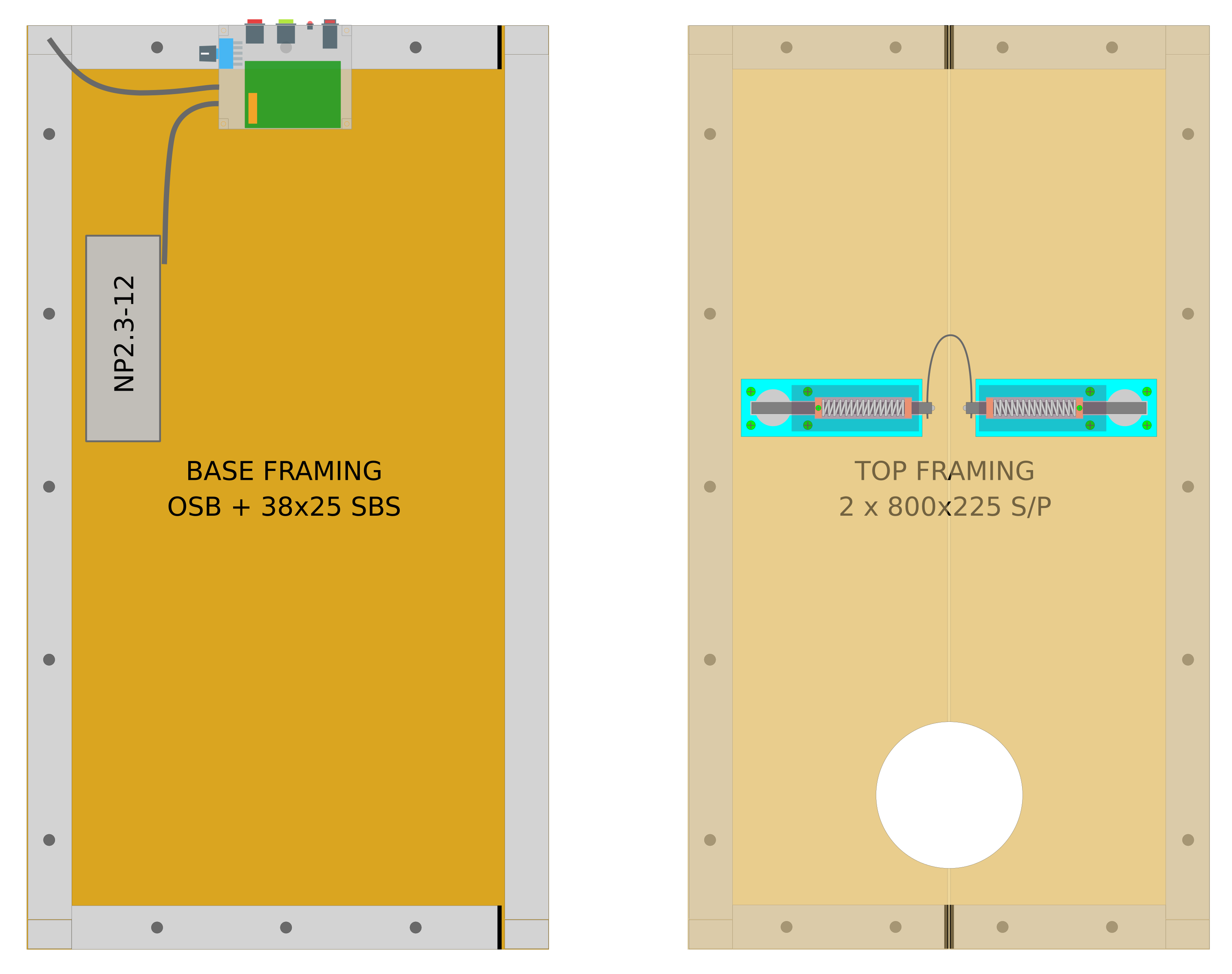
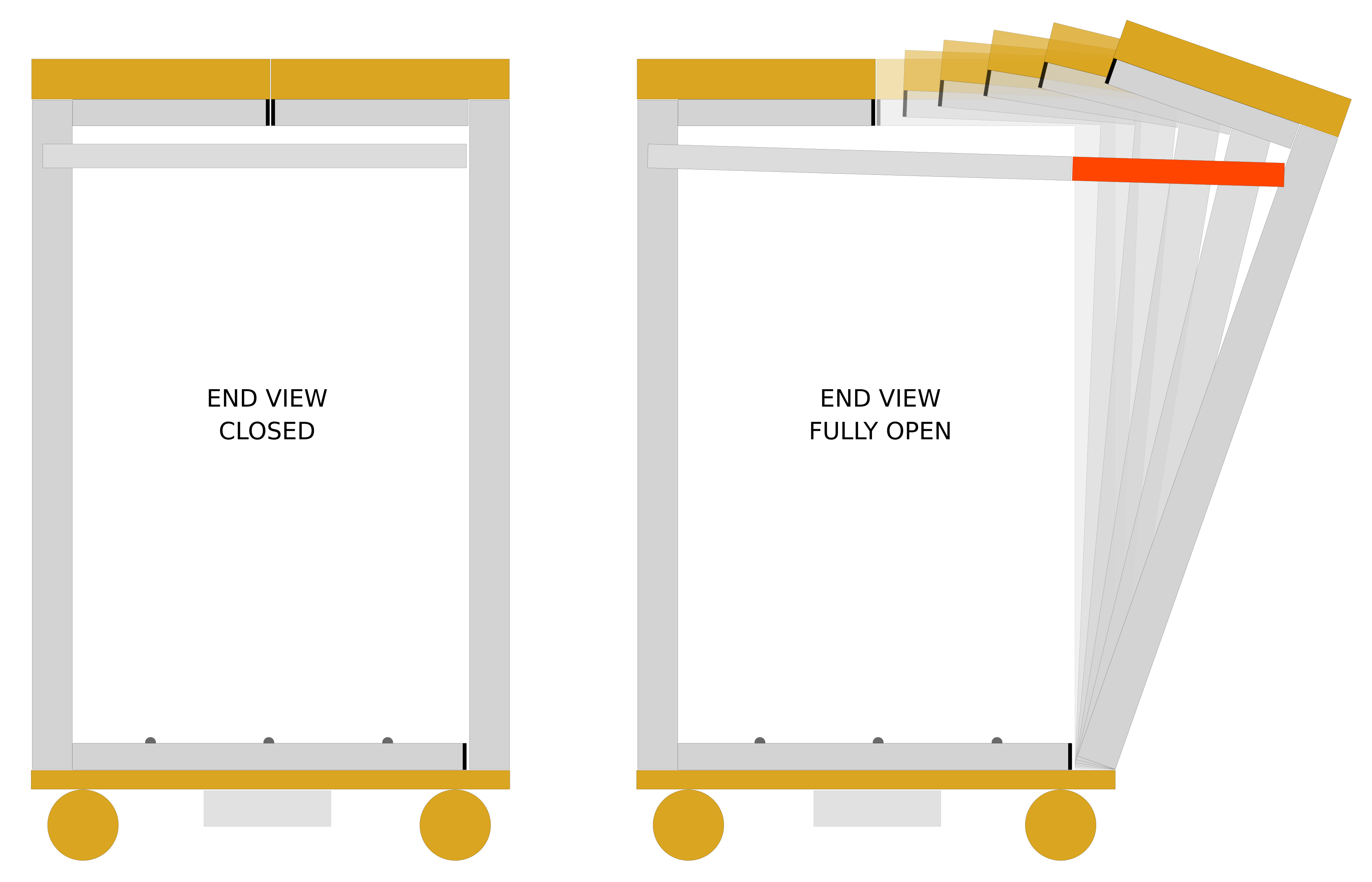
Bondage Furniture Project Build
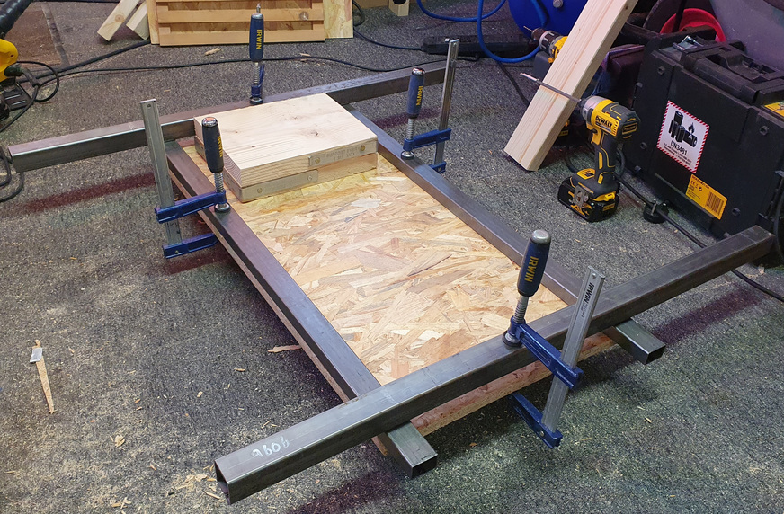
I wasn't exactly sure of the dimensions I needed, so a fair amount of time went into working them out. The width of the unit was constrained by the width of the two scaffold planks forming the top, each measuring 225mm giving a maximum of 450mm which I felt was perfectly adequate.
I was originally going to make it 800mm in length, but decided on 900mm having done some tests involving laying out steel box-section on a sheet of OSB (Oriented Strand Board) with me sat on top and working out where my feet finished - and also imagining if I were taller how that might look.
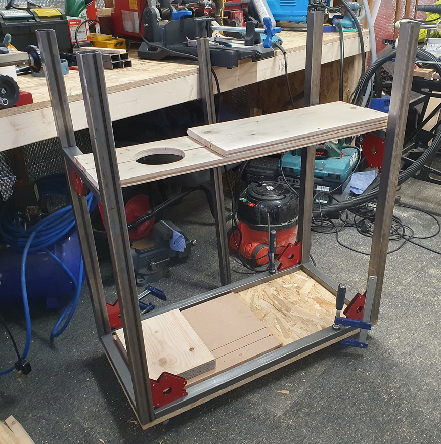
The height was more challenging as it needed to accommodate people of varying proportions. This was worked out by cutting a 127mm hole in a couple of tongue-and-groove floorboards and resting them on the frame in a 'test fit' state with everything held together by magnetic holders. I placed a couple of pieces of scrap wood to form a raised seat and carefully climbed inside and positioned the two floorboards around my neck and raised and lowered until I felt I'd found a suitable position. I figured the seat could be made height-adjustable, and this would provide a way of making the unit accommodate people between five-six and six-foot in height.
The 127mm neck hole is just the right size to accommodate my 14" neck and would be suitable for neck sizes up to 15.5". Any bigger and I'd need to re-cut with a 152mm hole saw, the next size up. If I were to make more contraptions in the future and had to offer a wider range of neck hole sizes I'd probably make up a series of router jigs for cutting them out.
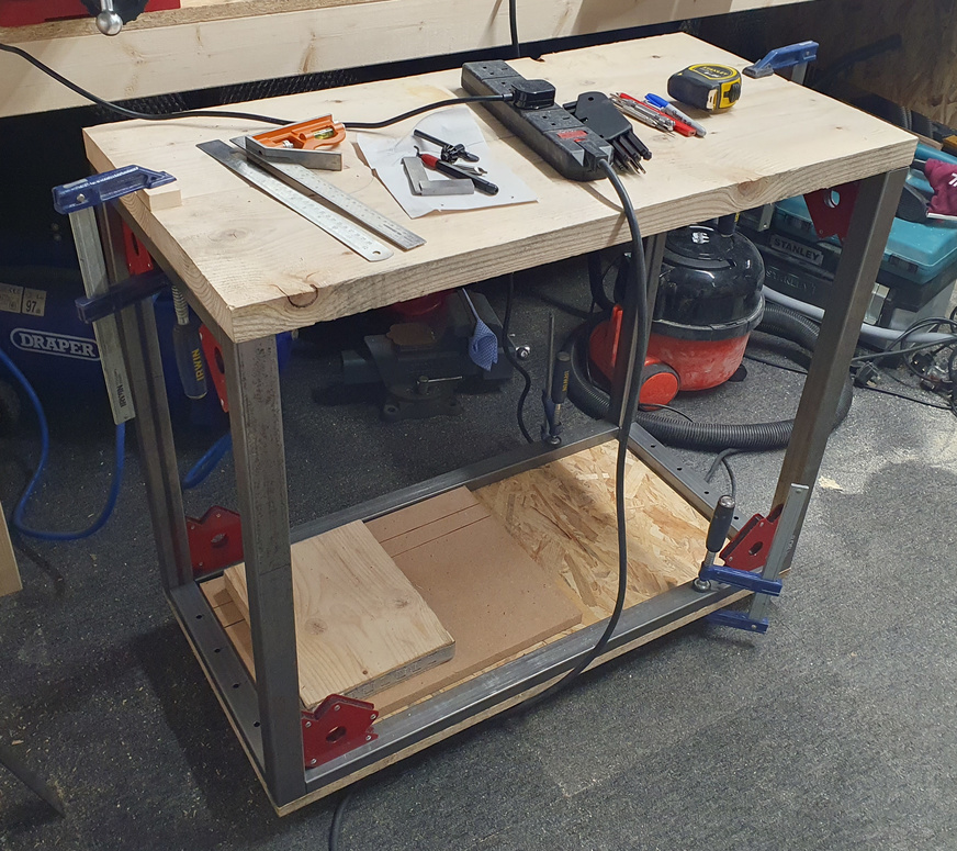
Having spent what seemed like days trying to decide on an ideal measurement - the distance between the top of the base and underside of the top - I finally decided that 70cm was the optimum value. I cut the four vertical columns down to this measurement and began cutting and shaping the two lengths of scaffold plank that would form the top.

With all the steel sections cut to length, test-fitted and mounting holes drilled, I was ready to start welding up the two portions of frame.

I picked up a pair of zinc-plated butt hinges from Wickes. One side would be welded to the moving section of steel frame and the other screwed down to the base board.
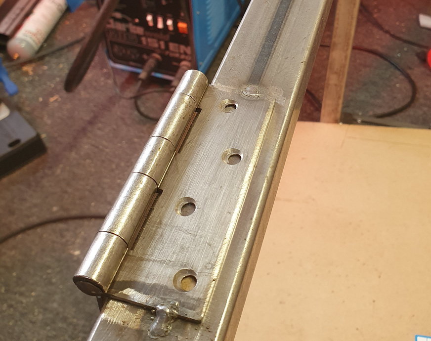
Here I've just placed a couple of tac welds to hold the hinge while I set it into a cut-out in the base board. Once I was happy it was in the correct position I placed a series of stitch welds along the three edges of the hinge.
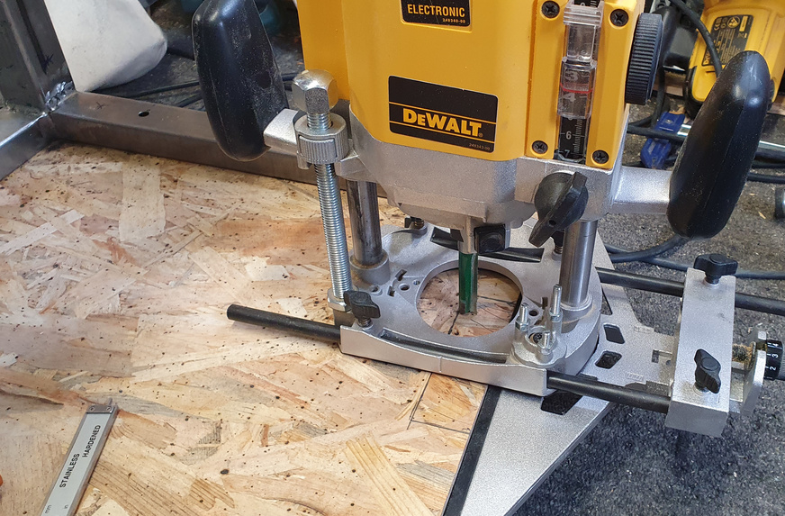
I setup the router to make a nice clean cut-out for the hinge, as they both needed to be at the same depth and sit level in the base board.
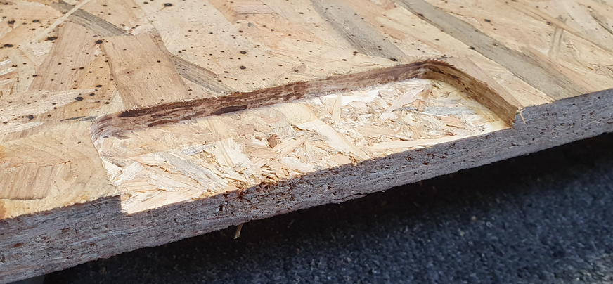
Doing this by hand with a chisel would never produce the accuracy required, and would most probably lead to the moving frame section being misaligned with the other.


Hinges installed and set in position, with the steel aligned and flush to the edge of the base board.

I made these wrist restraint catches from some 40mm flat steel, 10mm steel bar, and a couple of short lengths of 25mm square tube. The springs were cut from a long 30cm spring I'd ordered some months previously for another project. At a later stage the brass collars get replaced with lengths of 8mm steel bar, which are used to carry a steel cable linking the catches together.
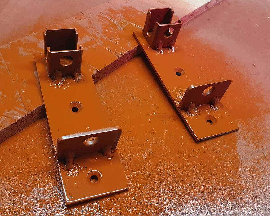
The wrist restraint catches taken apart and sprayed with red oxide primer.
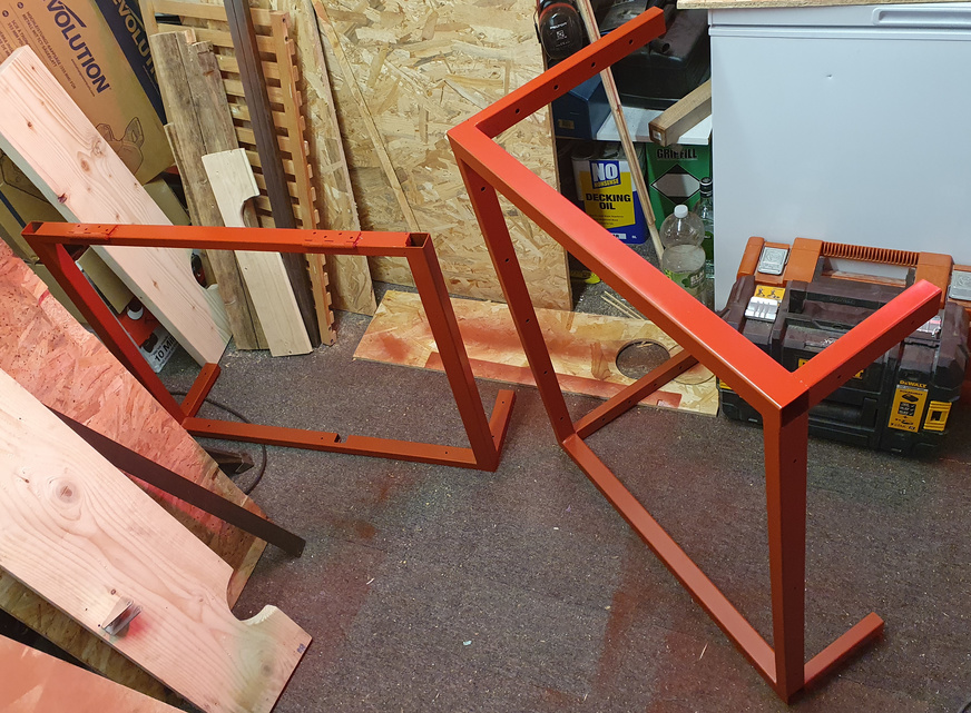
The steel frame was sanded with emery cloth and wet and dry sandpaper, then given a few coats of red oxide primer.

First assembly of the frame to the base board and mounting of the custom linear actuator controller I designed a few months earlier.

The linear actuator's mounted in place. I discovered it was slightly longer than what the frame would accommodate so I added a cut-out in the moving frame section. Thankfully I'd planned for this and made the cut prior to welding, so it was easily achieved by doing a series of cuts on the chop-saw.

Some testing to see if I'd made the frame the correct size and positioned the wrist restraint catches and actuator in the correct places.
The measurements I'd chosen at the beginning seem to work well. You can see there's plenty of room for accommodating my 5'9" frame, and by raising or lowering the seat people who're shorter or taller should fit too.
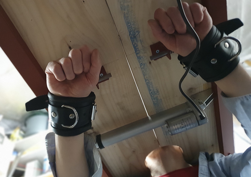
With the wrist restraint catches at this position it's difficult to reach any of the mechanical parts and it's comfortable too.

I made up two steel bars, each with a thread on one end for screwing into the sliding bolts of the catches. Each bar has a hole through which a steel cable can pass, but only one has an M4 machine screw in the end fixing the passing steel cable in place.
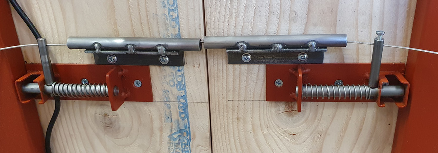
The steel cable connecting the two catches passes through two steel tubes, which makes the cable completely inaccessible and impossible to free a wrist restraint by grabbing and pulling on it.

The ankle restraint catch that's set in the base of the unit took some thinking about. The initial designs I drew up in Inkscape didn't include this part, as at the time I had no idea how it was going to work. It was one of those things I thought I'd figure out later.
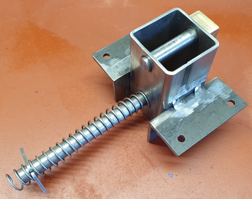
It consists of two 10mm diameter steel bars that pass through holes in a short length of 40mm steel box section, with each bar screwing into a short length of brass connecting them together. One bar is sprung and drives the other in and out of the box section. I welded on some steel angle iron to form brackets that mount the mechanism to the underside of the base board.
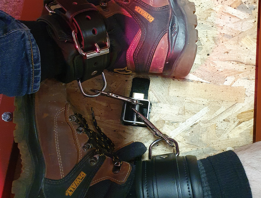
Some more testing.
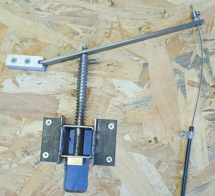
A cable-operated lever drives the sprung shaft which in turn moves the upper shaft to which restraints can be attached. A standard bike brake cable from Halfords was used, and transfers movement very smoothly.

The ankle restraint catch cable is operated by the parting of the top boards. The cable has been sleeved in a similar fashion to the wrist restraint catches, so as to prevent the cable being tampered with and operated by any fingers that might be able to reach it.
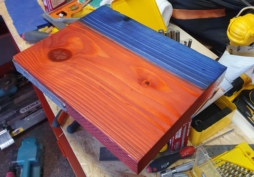
It took a while before I decided on a colour scheme. Initially I was trying to stay away from black and red, but having considered various colour options I circled right back to them. At one point I was considering making the top royal blue, so bought both the royal blue and red wood dye and applied them to a test piece.
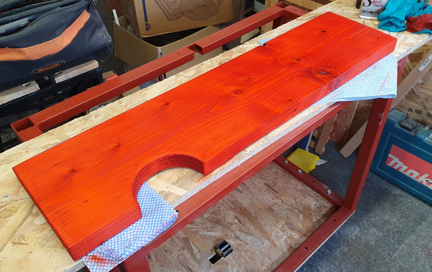
I definitely preferred the red finish so applied a few coats.
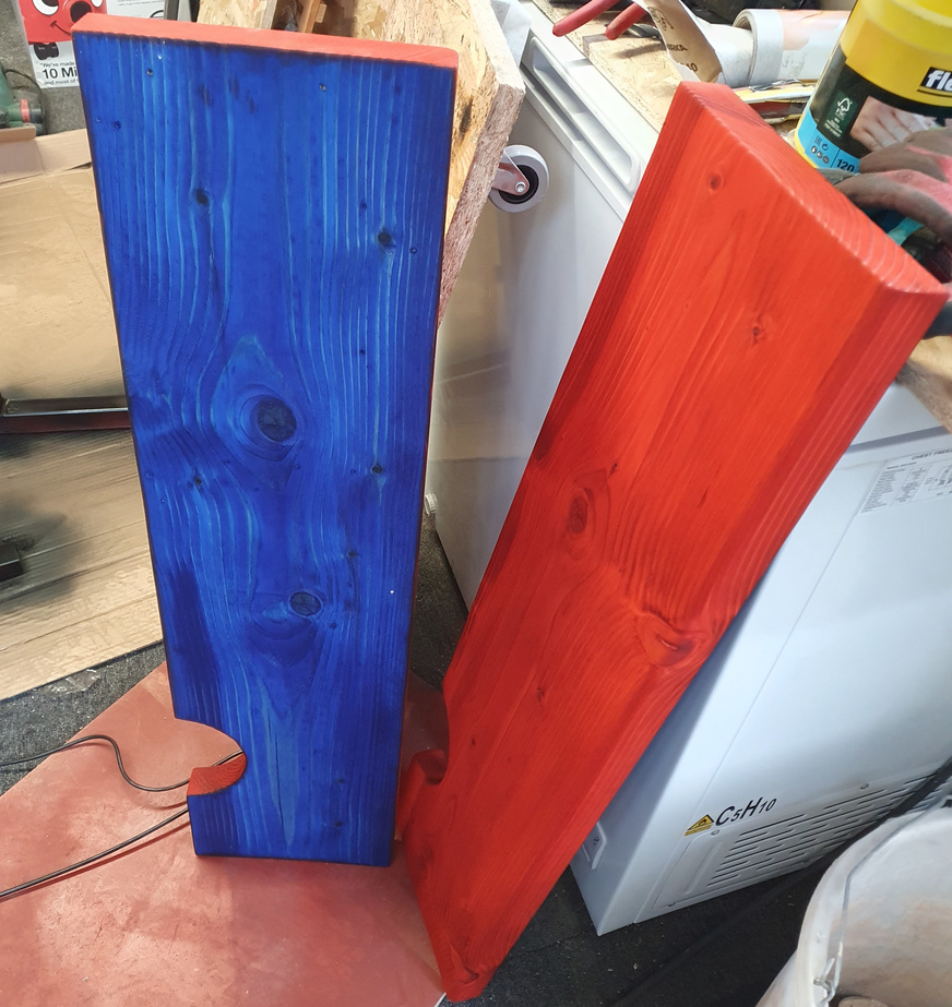
I still had loads of the royal blue dye left but was running low on the red, so decided to finished the underside with the blue.
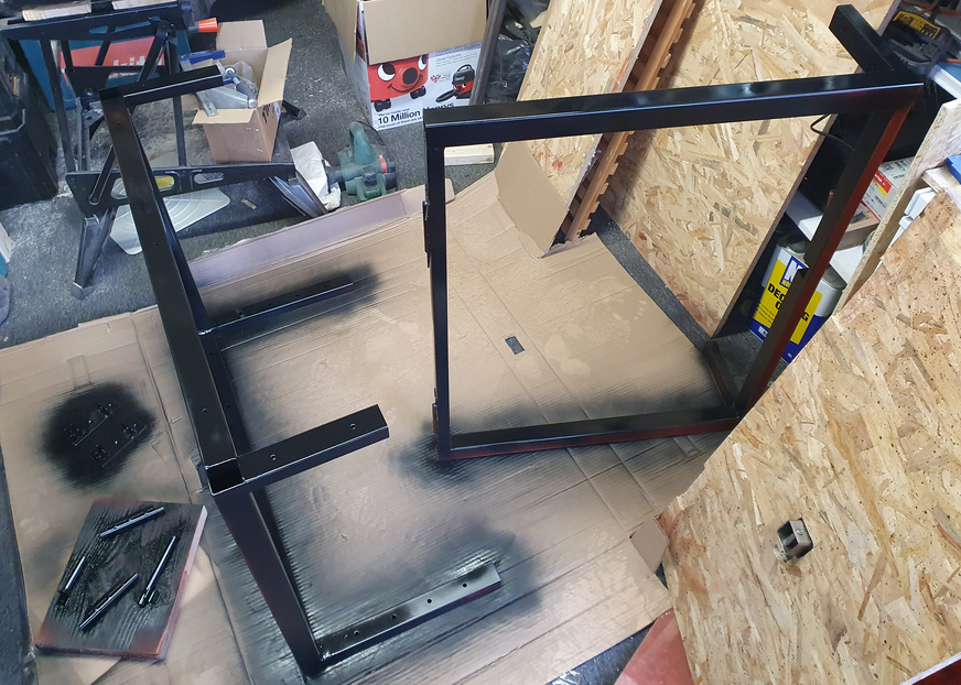
I dissembled all the metal parts and painted them satin black. I was trying to find someone locally who'd powder coat everything as this would be a much more durable finish, but nobody seemed interested as it's probably too small a job, so I went ahead with the spray paint. If it were a cage or some type of frame that might get things tied / strapped / locked to it then a powder coated finish would've been essential, and I would've put more effort into getting someone to do it.
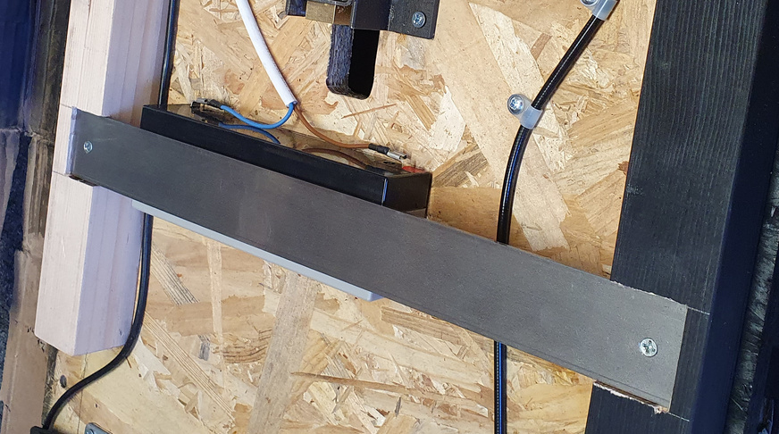
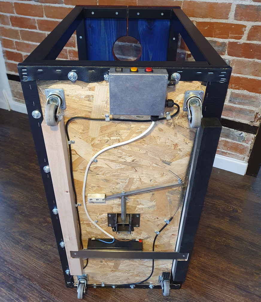
A Yuasa Y2.3-12 sealed lead acid battery is mounted to the underside of the base board using a length of flat steel. There's also doubled-sided tape on both sides of the battery so it can't work lose.
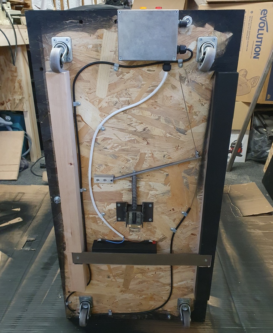
I fixed two lengths of wood to the underside, the main purpose of the one on the right was to provide a better fixing point for the hinge screws but also to prevent the hinged side of the board from flexing as it's not supported in this area by the steel frame. As this length of wood was closer to the edge of the board, and therefore quite visible, I painted it satin black same as the metal frame. The wood on the other side that's unpainted at this stage was to prevent the ankle restraint mechanism from either getting damaged or causing damage, should the unit be lifted through doorways or up a staircase. It later became apparent when mounting the battery that both lengths of wood were ideal fixing points for the flat steel that sandwiches the battery to the underside.
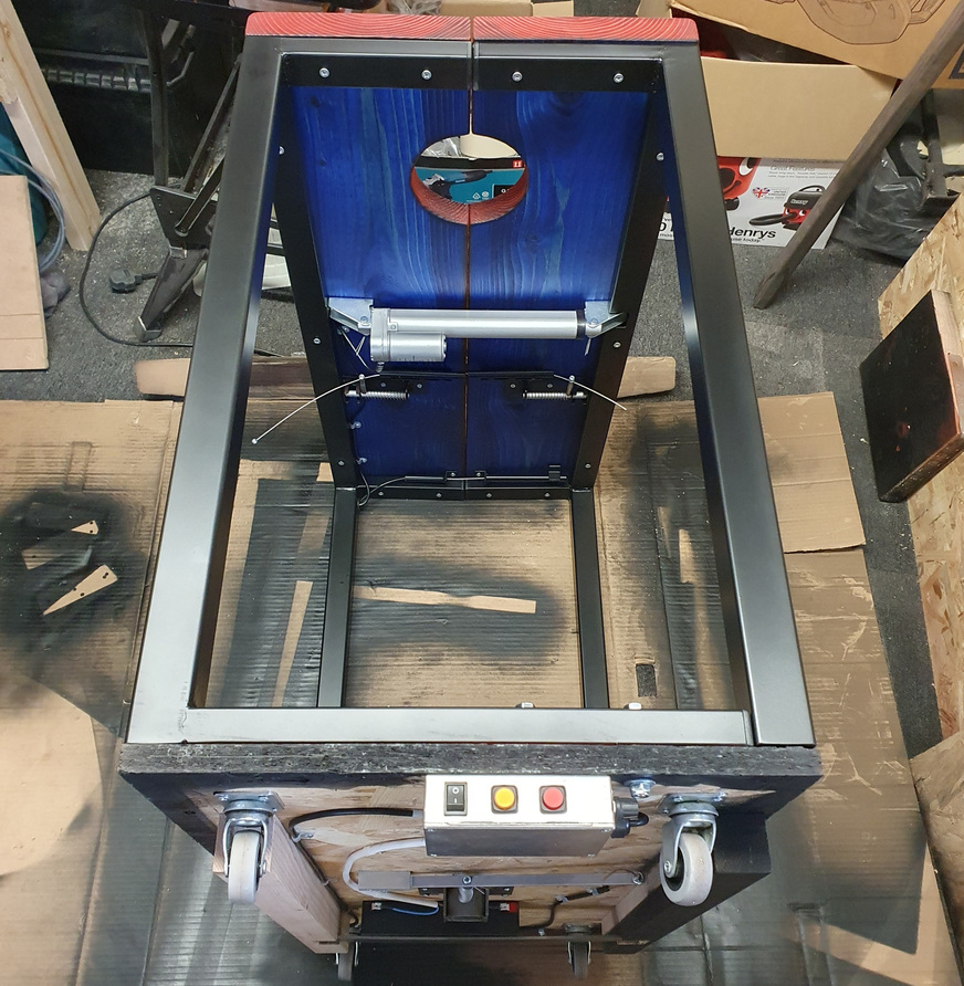
The unit reassembled and ready to be taken indoors from the workshop for some testing.
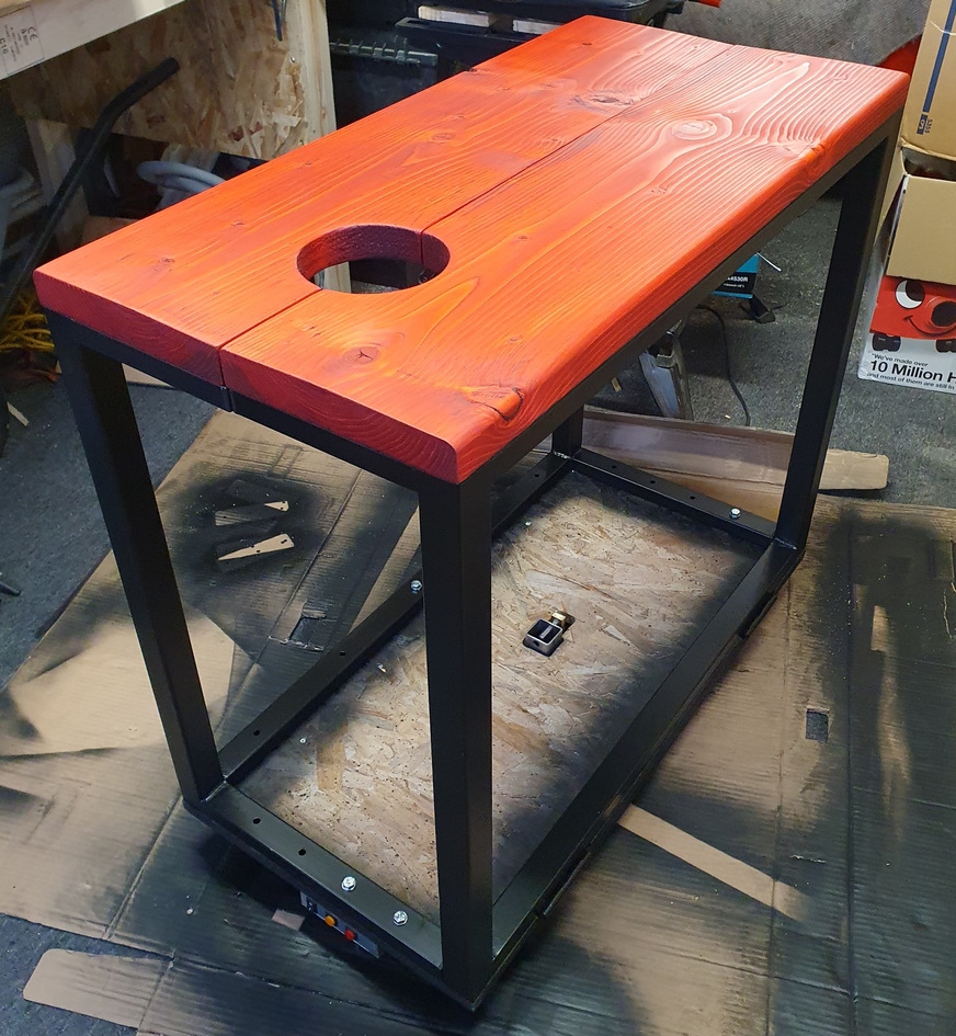
The red top was definitely the right choice. After I'd applied a few coats of the wood dye I finished it the following day with a few coats of tung oil to seal and protect the wood.

I dismantled the unit once more and took the base back out to the workshop to be vinyl wrapped. First I removed the ankle restraint catch and cut the hole square, then rounded the edges of the hole with a file and some sandpaper. Next I cleaned up all the outer edges and applied contact adhesive and started laying out the vinyl. Then I wrapped the edges and corners and stapled everything in position on the underside.
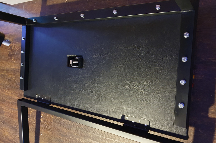
The base is now vinyl wrapped with the frame bolted back in place, it's pretty much finished at this stage and all that remains is to make up a comfortable seat.


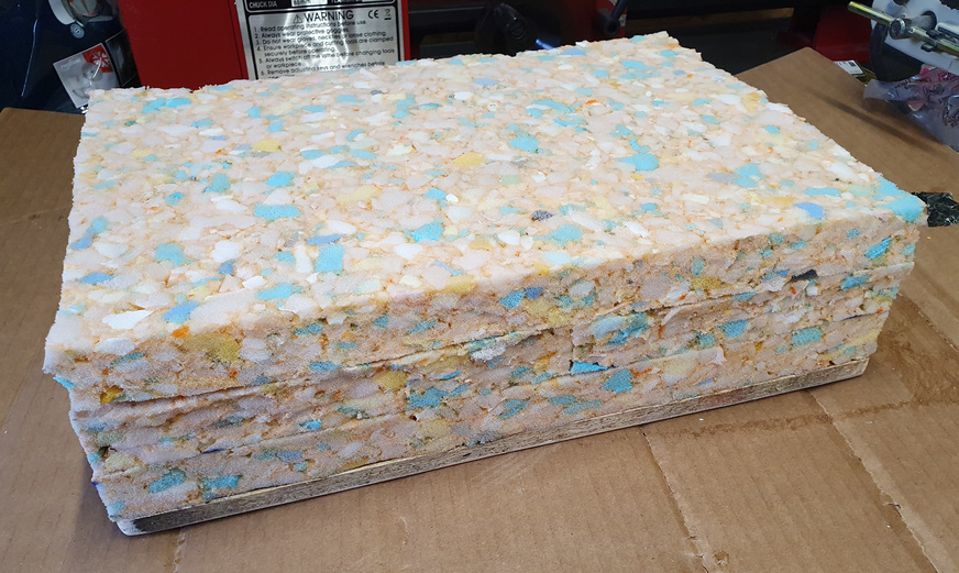
The seat was made from three layers of 1 inch reconstituted upholstery foam on an 11mm thick sheet of OSB, each layer bonded together with contact adhesive.

I drilled appropriately spaced holes in the OSB and mounted the four M8x60mm levelling feet which allow the seat height to be adjusted. Then vinyl wrapped the seat and fixed the vinyl to the underside with a combination of contact adhesive and staples.
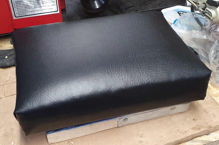
The finished seat, with the three inches of foam providing sufficient padding so that it remains comfortable for long periods of use.
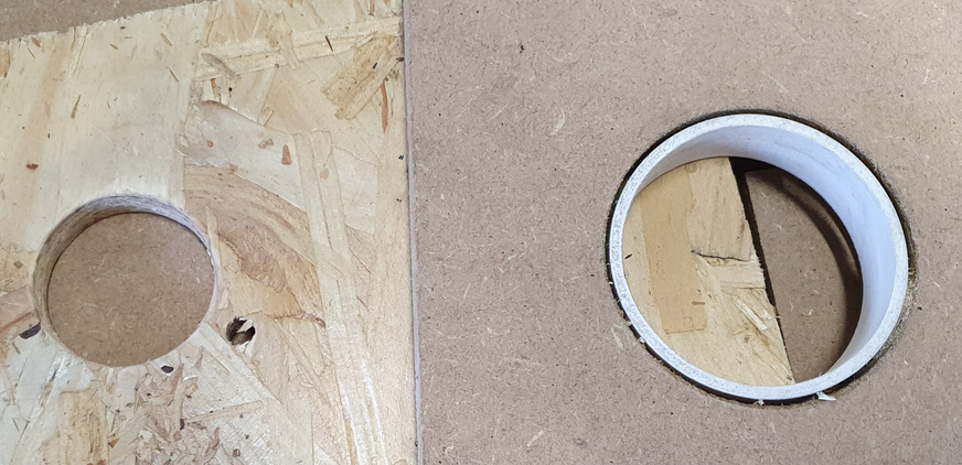
I found that in use the seat would slide about on the vinyl covered base, which wasn't ideal. I decided to make up a section of OSB with two precisely drilled 21mm holes spaced 254mm apart that would accept the rear feet of the seat. I didn't have a 21mm wood drill, and even if I did I imagine getting perfectly formed holes with the required spacing would be a challenge. So I decided to make up a router jig in order to cut the holes accurately and cleanly.
To make up the jig I first machined down the inside of a piece of PVC pipe to 56mm which would act as an initial jig for my router with a 30mm guide bush fitted. I hot-glued this plastic pipe section into a 63mm hole I cut in some scrap MDF using a 63mm hole saw I had to hand. Using my router with its 30mm guide bush in combination with the 56mm jig would allow me to cut the 38mm hole I needed in order to repeat the process and cut the required 21mm hole.
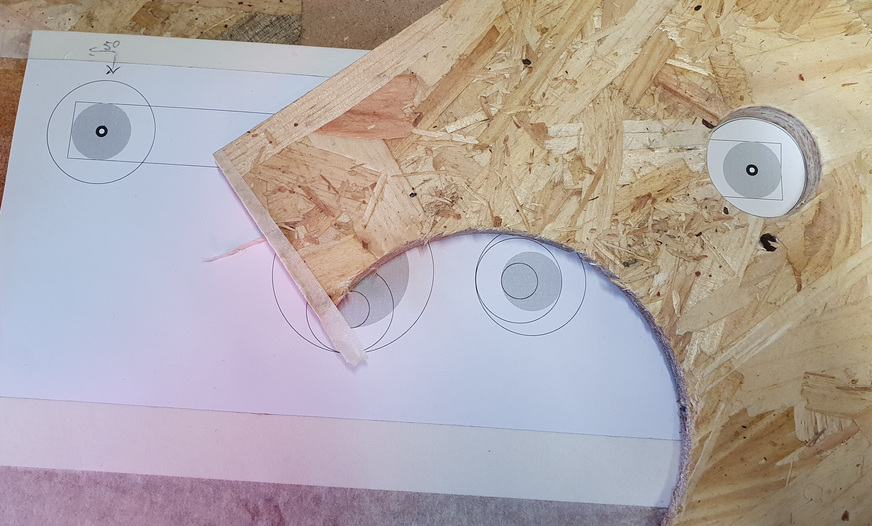
I used Inkscape to print a template of where the holes needed to be, and aligned the jig with the 38mm hole so I could use the router to cut the two 21mm holes in the finished piece.

First 21mm hole cut out using the 38mm jig.
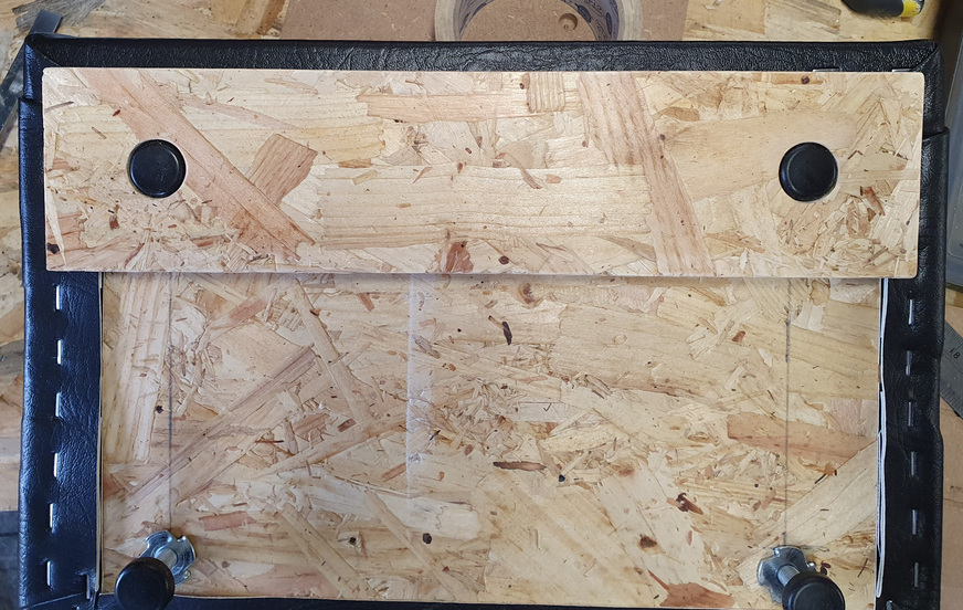
The machined piece of board accommodates the feet with minimal insertion resistance, and holds them in the exact position allowing no movement in any direction.
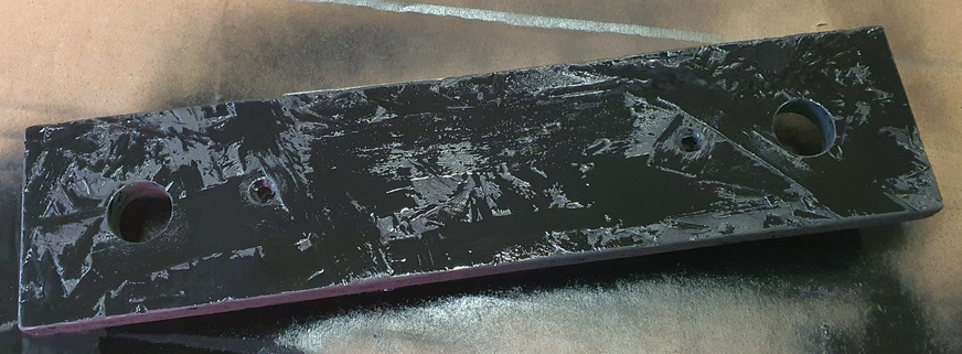
I sprayed the board black so it would blend in with the black vinyl once in position. It's screwed through the vinyl to the base board with two countersunk woodscrews.
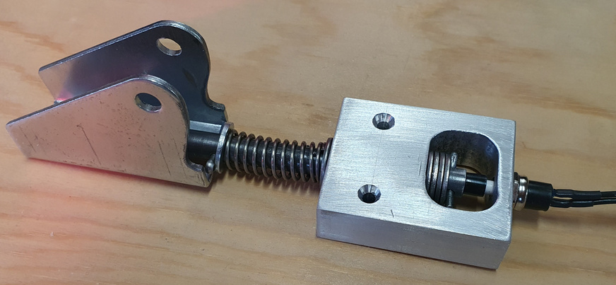
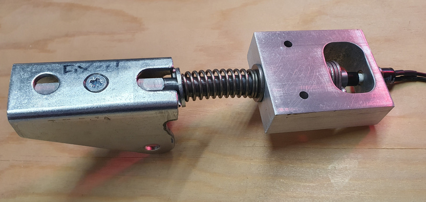
For safety purposes I made this jam switch to detect an obstruction when closing the contraption. This mechanism acts as an intermediary mounting between the wooden top and the actuator bracket, so when an object jams against the closing wooden panels the spring is compressed and the button fixed at the end is depressed. This completes the circuit of the jam switch connection on the control board, which immediately disables the open and close buttons for thirty seconds and drives the actuator to its fully extended / open position.
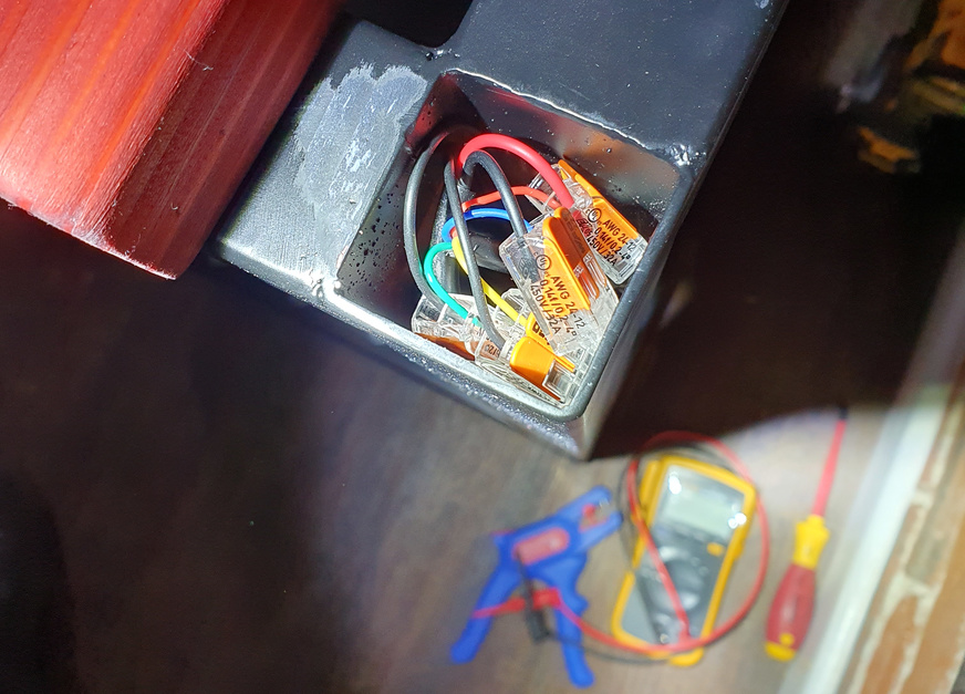
The black four-core cable from the control box runs along the underside of the base board and up through one of the vertical columns of the frame. Inside the top of the column it joins, via four Wago connectors, the cable for the actuator and the two wires for the jam switch.


The new safety jam switch mounted in position between the actuator bracket and wooden top. There's an additional microswitch that breaks the connection between the jam switch and control board (normally-closed contacts in series) disabling the switch when the contraption is fully closed. This prevents the jam switch being used to open the contraption by the restrained occupant, should they attempt pushing the two frames apart.
Finished Bondage Furniture Project, Testing in a Rubber Suit
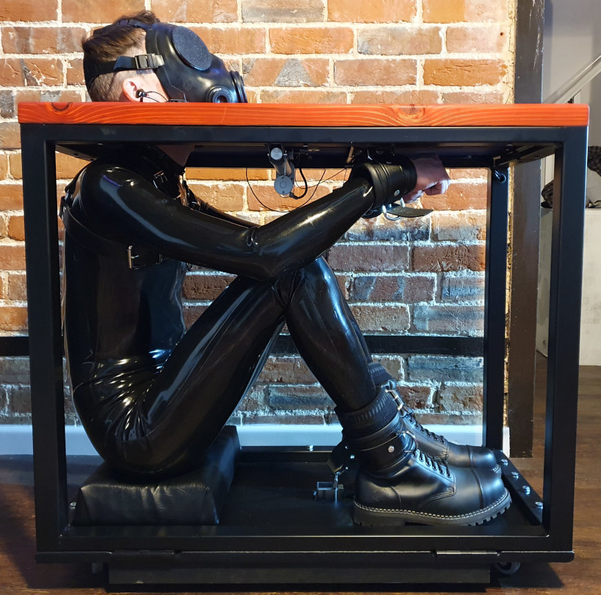
Some extensive endurance testing in a rubber suit and FM12 gas mask with blackout lens covers, just to make sure everything works exactly as it should!