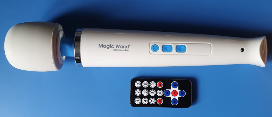
Here is a Magic Wand Rechargeable I've modified so it can be operated via remote control. The black dot in the lower portion of the handle is a TSOP4838 infrared sensor that connects to a supplementary control board inside.
Buttons 1,2,3,4 select the four basic vibration intensities, buttons 5,6,7,8 select the four vibration patterns, and zero turns the wand off. The up and down buttons enable the supplementary board to take full control of the wand's motor drive circuitry, and provides seventeen levels of intensity. The star button selects a custom vibration pattern, and the left and right buttons vary its speed.
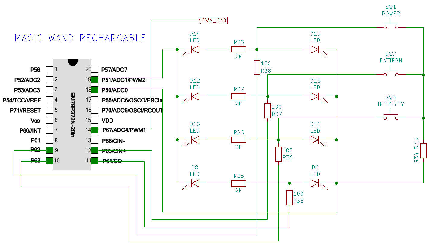
The schematic above shows how the three buttons and eight LEDs are connected to the Magic Wand's EM78 microcontroller. The buttons and LEDs are multiplexed so they take up only six I/O pins. The cathodes of the two strings of LEDs are connected to P50 and P51 which are used to select a string, then P62 to P65 are driven high to illuminate the required LED. During the multiplexing cycles P50 is changed from an output to an input, and its state is read while P62,P63,P65 are each pulsed high, to determine which, if any, of the three buttons is being pressed.
When I started this project I imagined each button and LED having its own pin, which would make it easy to identify which button had been pressed and which LED was illuminated, and therefore keep track of which setting the wand was using. This would be necessary in order for the remote control to keep in sync with any button presses on the wand itself. So for instance, if the wand had been turned on and set to its third intensity setting, and then the remote was used to select the fourth, the microcontroller would know it was already at level three and simply pulse the intensity button once.
The multiplexing of the buttons and LEDs makes it tricky to work out which setting the wand is using. To get around this problem and make the remote control operate the wand seamlessly with the physical buttons, every time the remote control module receives a command it turns off the wand, then turns it back on and pulses the buttons in whatever order required - thus no keeping track of the current setting is necessary. To pulse the buttons and select the correct setting the module has to determine whether the wand is currently on, as in order to turn it off and on again two pulses to the power button would be required, instead of just one pulse if it was already off.
This means the wand can be controlled by interfacing just the three buttons, which is achieved - due to the multiplexing - by the use of the three optocouplers as shown in the schematic below.
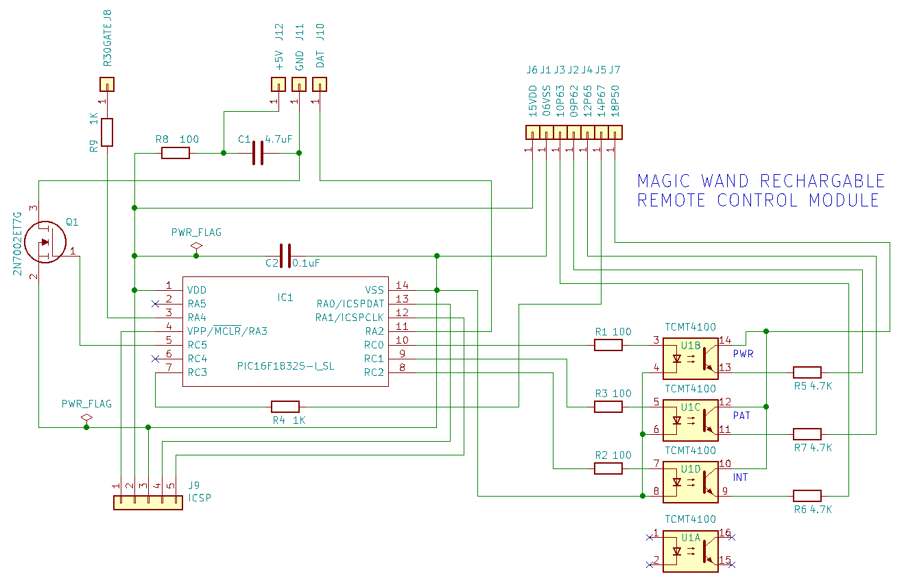
The 4.7K resistors R5,R6,R7 serve the function of the single 5.1K R34 in the first wand schematic above. This resistor prevents button presses from creating a short between P50 and the four output pins that drive the LEDs when P50 is set to an output, but is adequate to drive P50 high when set as an input to read button presses.
Pin-14 (P67/PWM1) on the EM78 is used to control the motor via pulse width modulation, and is connected to the gate of the NCE3010 N-channel MOSFET via a 1K resistor R30 on the underside of the mainboard. In order for the supplementary remote control module to take full control of the motor I've removed R30 and connected the pad going to the MOSFET's gate, via a 1K resistor, to the digital output RA4 of the PIC microcontroller. The disconnected PWM output from pin-14 of the EM78 is now connected to RC3/C1IN3- so the EM78's PWM signal can drive the negative input of the C1 comparator module.
When we want the EM78 to control the motor it's simply a matter of enabling the C1 comparator module, and then using the Peripheral Pin Select (PPS) module to assign the output of the comparator to RA4. With the Fixed Voltage Reference (FVR) supplying 2.048v to the comparator's positive input, and the comparator configured so its output is inverted, the waveform produced on RA4 will be symmetrical to the incoming PWM signal from the EM78.
To control the motor independently of the EM78 the comparator module is disabled, and output from the Capture/Compare/PWM module CCP1 is assigned to RA4 instead. The CCP1 module is then enabled and a value written to the CCPR1H/CCPR1L register pair which sets the duty-cycle of the PWM waveform now present on RA4. The duty-cycle, and therefore motor speed, can be altered at any point by calling the set_pwm_duty() function with the desired percentage.
The presence of a PWM signal on RC3 determines the power state of the Magic Wand, and the get_wand_power_state() function is used to periodically check for either a low-state or positive-going transition on this pin. After a period of twenty minutes the wand's power state is checked using this method, and if it's found to be inactive the PIC will enter sleep mode. Before entering sleep, Interrupt On Change for RC3 is enabled so that the PIC can be woken when the wand is turned back on.
When in a sleep state, power to the TSOP4838 IR sensor (not shown on the schematic, connected to J10,J11,J12) is shut off by setting RC5 low, which turns off the 2N7002 MOSFET Q1. This reduces the module's power consumption to less than half a microamp.
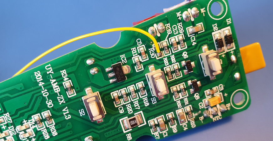
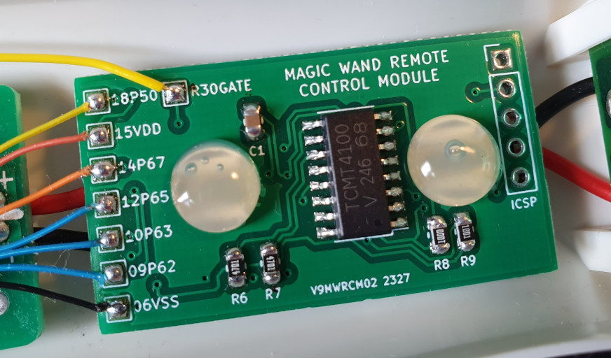
Here's the position of the 1K resistor R30. The connected pad goes to the gate of the NCE3010 N-channel MOSFET Q9 (on the other side of the board) which drives the motor. The unconnected pad goes directly to pin-14 (P67) of the EM78. The yellow wire connects to the pad labled R30GATE on the remote control module.
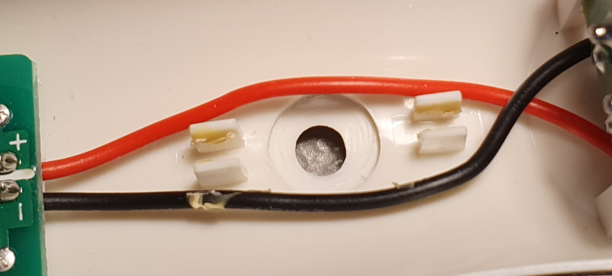
A 4.5mm hole was drilled between the power cable support tabs for the lens of the TSOP4838 IR sensor, then a 10mm end mill was used to cut a recess for the flat surface around the lens.
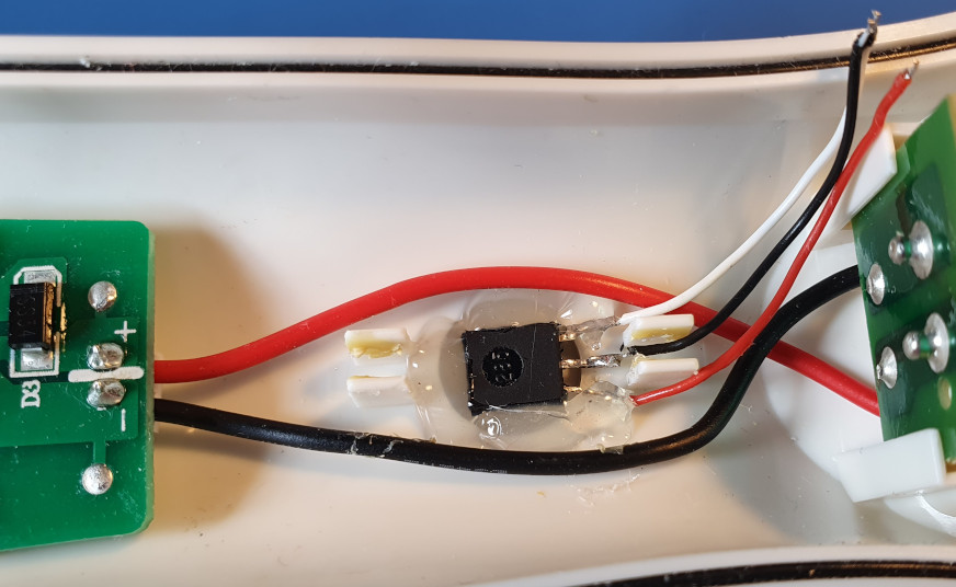
Some short leads were soldered to the pins of the sensor, and then the sensor was secured in place with hot glue.
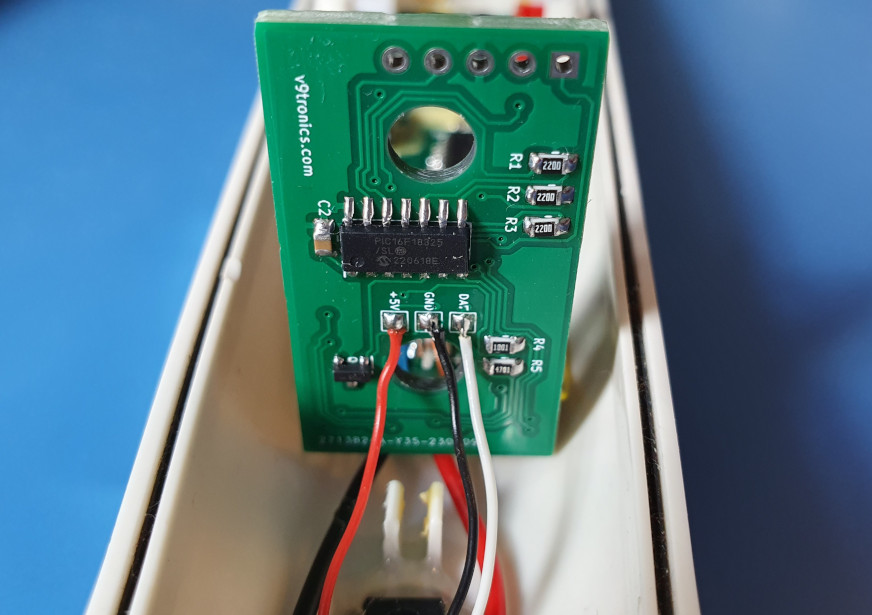
The other ends of the leads were soldered onto the corresponding pads on the underside of the PCB.
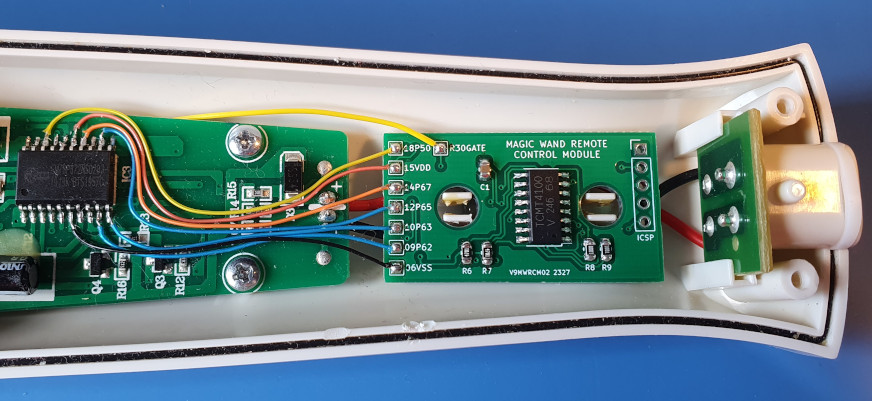
The PCB, measuring 21x38mm, fits neatly in the only available space in the handle. The board mounts on top of the plastic tabs which support the wires coming from the power socket. The TCMT4100 quad optocoupler is the SSOP-16 on the top of the board, the PIC16F18325 and 2N7002 MOSFET are mounted on the underside.
Once all the necessary connections had been made, I reconnected the battery and programmed the PIC microcontroller using a PICKIT4. Having tested the module to make sure it operated correctly I secured it in place by applying a blob of hot glue to each of the mounting tabs.
Complete code listing for use with PIC16F18325, compiled using MPLAB X IDE V5.15 and XC8 V2.10
/*
* File: magic_wand_remote_control.c
* Author: paul reynolds ( paul at v9tronics d0t c0m )
*
* This is the complete code for the Magic Wand Remote Control Module. It allows the four intensities
* and four vibration patterns to be selected using a standard NEC infrared remote control.
*
* Buttons 1,2,3,4 select the four intensities, buttons 5,6,7,8 select the four vibration patterns, and
* 0 turns off. The up and down buttons allow us to take control of the motor and adjust its speed to
* one of seventeen steps. The star button is used to select a custom vibration pattern, which can be
* modified using the arrow buttons - this requires further development, only one custom pattern has be
* created so far.
*
* Due to the multiplexing of the six I/O pins (that handle the eight LEDs and three buttons) there's no easy
* way to determine which of the eight settings the wand is using. This means we could lose synchronisation
* if one of the actual buttons were to be pressed and the remote control was used after. To circumvent
* this problem, each time a setting is selected via the remote control a sequence of button presses are
* performed that'll turn off, turn back on, and then pulse either the intensity or pattern button to
* navigate to the desired setting.
*
* The only input from the EM78 is the motor drive PWM signal on Pin-14 which provides a constant square-wave
* when the wand is active / powered on. This signal is used to determine the power state of the wand so the
* correct button sequence can be applied, to allow the PIC to sleep after a (twenty minute) period of
* inactivity, and to wake the PIC from a sleep state when the wand becomes active again. The PWM signal from
* the EM78 is also used to drive the negative input of the C1 comparator module, which allows us to pass the
* signal through to the motor drive circuitry (via RA4) when we want the EM78 to control the motor.
*
* When we want to control the motor independently of the EM78, the Peripheral Pin Select module is used to
* assign the output of the CCP1 (Capture/Compare/PWM1) module to RA4, in place of the output from the C1
* comparator. We can then use CCP1 to generate a substitute 10kHz PWM signal and vary its duty-cycle to
* control the motor speed.
*
* Timer0 is used to increment the SLEEP_TIMER every minute. Once it has been incremented to twenty the wand
* power state is checked, and if found to be inactive the PIC enters a low-power sleep state. When in this
* state RC5 goes low, turning off the MOSFET (Q1) powering the TSOP4838 infrared sensor, which reduces power
* consumption of the module to approximately 0.43uA.
*
* Created: 1st JUNE 2023
*
* Revised: 8th JULY 2023
*/
// PIC16F18325 Configuration Bit Settings
// 'C' source line config statements
// CONFIG1
#pragma config FEXTOSC = OFF // FEXTOSC External Oscillator mode Selection bits (Oscillator not enabled)
#pragma config RSTOSC = HFINT32 // Power-up default value for COSC bits (HFINTOSC (32MHz))
#pragma config CLKOUTEN = OFF // Clock Out Enable bit (CLKOUT function is disabled; I/O or oscillator function on OSC2)
#pragma config CSWEN = ON // Clock Switch Enable bit (Writing to NOSC and NDIV is allowed)
#pragma config FCMEN = OFF // ON //Fail-Safe Clock Monitor Enable (Fail-Safe Clock Monitor is enabled)
// CONFIG2
#pragma config MCLRE = ON // Master Clear Enable bit (MCLR/VPP pin function is MCLR; Weak pull-up enabled)
#pragma config PWRTE = OFF // Power-up Timer Enable bit (PWRT disabled)
#pragma config WDTE = OFF // Watchdog Timer Enable bits (WDT enabled, SWDTEN is ignored)
#pragma config LPBOREN = ON //OFF // Low-power BOR enable bit (ULPBOR disabled)
#pragma config BOREN = SLEEP // Brown-out Reset is enabled while running, disabled in Sleep
#pragma config BORV = LOW // Brown-out Reset Voltage selection bit (Brown-out voltage (Vbor) set to 2.45V)
#pragma config PPS1WAY = ON // PPSLOCK bit One-Way Set Enable bit (The PPSLOCK bit can be cleared and set only once; PPS registers remain locked after one clear/set cycle)
#pragma config STVREN = ON // Stack Overflow/Underflow Reset Enable bit (Stack Overflow or Underflow will cause a Reset)
#pragma config DEBUG = OFF // Debugger enable bit (Background debugger disabled)
// CONFIG3
#pragma config WRT = OFF // User NVM self-write protection bits (Write protection off)
#pragma config LVP = ON // Low Voltage Programming Enable bit (Low Voltage programming enabled. MCLR/VPP pin function is MCLR. MCLRE configuration bit is ignored.)
// CONFIG4
#pragma config CP = OFF // User NVM Program Memory Code Protection bit (User NVM code protection disabled)
#pragma config CPD = OFF // Data NVM Memory Code Protection bit (Data NVM code protection disabled)
#define _XTAL_FREQ 32000000
#include <xc.h>
#include <stdio.h>
#include <stdlib.h>
#include <string.h>
/*
* PIC16F18325
* [+++] [---]
* [RA5] [RA0]
* [RA4] [RA1]
* [RA3] [RA2]
* [RC5] [RC0]
* [RC4] [RC1]
* [RC3] [RC2]
*
* O RA0 > UART_TX_OUT, DEBUG ON ICSP:PIN4
* I RA2 > TSOP4838, IR DATA IN
* O RA3 > N/C
* O RA4 > PWM OUT, MOTOR DRIVE CIRCUITRY
* O RA3 > N/C (MCLR)
* O RC0 > EM78-PIN 09, POWER BTN
* O RC1 > EM78-PIN 12, PATTERN BTN
* O RC2 > EM78-PIN 10, INTENSITY BTN
* I RC3 > EM78-PIN 14, PWM SIGNAL
* O RC4 > N/C
* O RC5 > 2N7002 GATE, POWER TSOP4838
*/
#define IR_SENSOR_DAT PORTAbits.RA2 // TSOP4838 INPUT
#define EM78_09_POWER PORTCbits.RC0 // TCMT4100 U1B
#define EM78_12_PATTERN PORTCbits.RC1 // TCMT4100 U1C
#define EM78_10_INTENSITY PORTCbits.RC2 // TCMT4100 U1D
#define EM78_14_PWM_STATE PORTCbits.RC3 // EM78 PWM INPUT
#define IR_SENSOR_PWR PORTCbits.RC5 // 2N7002 Q1 GATE
#define OUR_PWM_SIGNAL CCP1CONbits.CCP1EN // OUR PWM ON RA4
#define _ON_ 1
#define _OFF_ 0
#define START 1
#define STOP 0
#define TRUE 1
#define FALSE 0
#define REMOTE_BTN_0 0x19
#define REMOTE_BTN_1 0x45
#define REMOTE_BTN_2 0x46
#define REMOTE_BTN_3 0x47
#define REMOTE_BTN_4 0x44
#define REMOTE_BTN_5 0x40
#define REMOTE_BTN_6 0x43
#define REMOTE_BTN_7 0x07
#define REMOTE_BTN_8 0x15
#define REMOTE_BTN_9 0x09
#define REMOTE_BTN_OK 0x1C
#define REMOTE_BTN_LT 0x08
#define REMOTE_BTN_RT 0x5A
#define REMOTE_BTN_UP 0x18
#define REMOTE_BTN_DN 0x52
#define REMOTE_BTN_ST 0x16 // star
#define REMOTE_BTN_HA 0x0D // hash
//
// infra-red remote decoding variables
//
unsigned int ir_pos = 0;
unsigned int ir_dat[67];
unsigned int ir_cnt = 0;
unsigned int ir_decode = 0;
//
// counters for timing things
//
int counter_a = 0;
int counter_b = 0;
//
// main system variables
//
int SLEEP_TIMER = 0;
int MOTOR_PWM = 50;
int VIB_PATTERN = 0;
//
// store time between transitions (on INT/TSOP4838 data pin) in an array
//
void get_ir_data(){
ir_cnt = 0;
ir_pos = 0;
int ir_pin_val_old;
int ir_pin_val;
ir_pin_val_old = IR_SENSOR_DAT;
while(1){
ir_pin_val = IR_SENSOR_DAT;
if( ir_pin_val == ir_pin_val_old ){
// increment cnt if pin_val remains unchanged
ir_cnt ++;
}else{
// pin_val has changed, so store cnt and move to next position
ir_dat[ir_pos] = ir_cnt;
ir_pos ++;
// store new pin_val and reset cnt, ready to go again
ir_pin_val_old = ir_pin_val;
ir_cnt = 0;
}
// exit if there's no more data
if( IR_SENSOR_DAT == 1 && ir_cnt > 1000 ){ break; }
}
ir_decode = TRUE;
}
//
// interrupt service routine
//
void __interrupt () isr_routine (void){
// incoming infrared data on INT disables interrupts, then calls
// get_ir_data() which takes care of storing the incoming data
if( PIR0bits.INTF == 1 ){
// disable global and peripheral interrupts and INT while we process the data
// these get re-enabled after we've processed the command
INTCONbits.GIE = FALSE;
INTCONbits.PEIE = FALSE;
PIE0bits.INTE = FALSE;
get_ir_data();
}
// timer zero is used to increment the sleep timer
if( PIR0bits.TMR0IF == 1 ){
// increment the sleep timer every minute
if( counter_a >= 450 ){
SLEEP_TIMER ++;
counter_a = 0;
}
counter_a ++;
PIR0bits.TMR0IF = 0;
}
// when the wand is active EM78_PIN14 (connected to IOC3/RC3) has a PWM signal driving the
// motor, it's low when the wand is off - so wake and clear timer when a rising-edge occurs
if( IOCCFbits.IOCCF3 == 1 ){
IOCCFbits.IOCCF3 = 0; // clear flag for RC3 Interrupt On Change
PIR0bits.IOCIF = 0; // clear IOC flag
SLEEP_TIMER = 0; // reset the sleep timer, as the wand is now active
}
}
//
// reset the sleep counter
//
void reset_sleep_timer(){
SLEEP_TIMER = 0;
counter_a = 0;
}
//
// determine power state of magic wand - EM78_14_PWM active when on and low when off
//
int get_wand_power_state( void ){
int state = _OFF_;
int x = 0;
while( x < 2000 ){
if( EM78_14_PWM_STATE == TRUE ){
state = _ON_;
break;
}
x++;
}
return state;
}
//
// pulse the buttons using three channels of the TCMT4100 quad OPTOCOUPLER
//
void pulse_power( int times ){
int repeat = 0;
while( repeat < times ){
EM78_09_POWER = _ON_;
__delay_ms(100);
EM78_09_POWER = _OFF_;
__delay_ms(100);
repeat ++;
}
}
void pulse_intensity( int times ){
int repeat = 0;
while( repeat < times ){
EM78_10_INTENSITY = _ON_;
__delay_ms(100);
EM78_10_INTENSITY = _OFF_;
__delay_ms(100);
repeat ++;
}
}
void pulse_pattern( int times ){
int repeat = 0;
while( repeat < times ){
EM78_12_PATTERN = _ON_;
__delay_ms(100);
EM78_12_PATTERN = _OFF_;
__delay_ms(100);
repeat ++;
}
}
//
// calls with anything greater than zero isolates EM78_PWM by assigning RA4(PPS) to CCP1
// and we use CCP1 to generate our substitute 10kHz PWM signal
//
// zero assigns RA4(PPS) back to the output of C1, so we can pass the PWM signal from the EM78
//
void set_pwm_duty( int pwm_duty_pc ){
if( pwm_duty_pc == 0 ){
CM1CON0bits.C1ON = TRUE; // enable C1 comparator
RA4PPS = 0b10110; // RA4 output source is C1 (Comparator1 - pass-through EM78 PWM)
OUR_PWM_SIGNAL = FALSE; // disable CCP1 (CCP1CONbits.CCP1EN) PWM output
}
int ccp_val = (~pwm_duty_pc + 100) * 8 + 8;
int lo_byte = ccp_val & 0xff;
int hi_byte = ccp_val >> 8;
CCPR1L = lo_byte;
CCPR1H = hi_byte;
if( pwm_duty_pc > 0 ){
CM1CON0bits.C1ON = FALSE; // disable C1 comparator
RA4PPS = 0b01100; // RA4 output source is CCP1 (Capture/Compare/PWM1 - our PWM)
OUR_PWM_SIGNAL = TRUE; // enable CCP1 (CCP1CONbits.CCP1EN) PWM output
}
}
void main(){
// OSCILLATOR CONFIG @ 32MHz
OSCCON1bits.NOSC = 0b000; // HFINTOSC with 2x PLL
OSCCON1bits.NDIV = 0b0000; // divide by 1
OSCFRQbits.HFFRQ = 0b110; // 2x16=32MHz
OSCENbits.HFOEN = 1; // enable high-frequency oscillator
CPUDOZEbits.IDLEN = 0; // sleep instruction places the device into full-sleep mode
VREGCONbits.VREGPM = 1; // low-power sleep mode enabled in sleep
// PIN CONFIG
TRISA = 0b00000100; // outputs except RA2/TSOP4838_DAT
ANSELA = 0b00000000; // all digital pins
TRISC = 0b00001000; // outputs except RC3/EM78_14_PWM
ANSELC = 0b00000000; // all digital pins
WPUAbits.WPUA3 = 1; // enable weak pull up on RA3 (MCLR)
// UART CONFIG - NOT USED
SYNC = 0; // disable for asynchronous EUART
SPEN = 0; // enables the EUSART and sets TX/CK I/O pin as output
TXEN = 0; // enables transmitter
CREN = 0; // enables receiver
TX9 = 0; // set to 8bit transmit
RX9 = 0; // set to 8bit receive
RA0PPS = 0b10100; // peripheral pin setup - UART TX is on RA0 (ICSP:PIN4)
// UART BAUD RATE CONFIG - NOT USED
BRGH = 0; // baud rate generator - !high baud rate
BRG16 = 0; // baud rate generator - 8 bit operation
SPBRG = 51; // baud rate generator - 9600@32MHz
SENDB = 1; // send break character
// INTERRUPT CONFIG
INTCONbits.INTEDG = 1; // interrupt on INT RISING edge
PIR0bits.INTF = 0; // reset INT interrupt flag
PIE0bits.INTE = 1; // enable INT interrupt
PIE0bits.IOCIE = 0; // disable IOC interrupt - enabled when required
IOCCPbits.IOCCP3 = 1; // enable IOC RC3 positive edge detection
INTCONbits.GIE = 1; // global interrupt enable
INTCONbits.PEIE = 1; // peripheral interrupts enable
// ADC CONFIG - NOT USED
ADCON0bits.ADON = 0; // turn on/off ADC
// TIMER0 CONFIG - for driving sleep timer
T0CON0bits.T0EN = 1; // timer 0 enabled
T0CON0bits.T016BIT = 0; // an 8 bit timer
T0CON0bits.T0OUTPS = 0b1111; // 1:16 post-scaler
T0CON1bits.T0CS = 0b010; // FOSC/4
T0CON1bits.T0CKPS = 0b1000; // pre-scaler 1:256
T0ASYNC = 0;
TMR0L = 0;
TMR0IE = 1; // enable the Timer 0 interrupt
// COMPARATOR1 (C1) CONFIG - to pass incoming PWM signal through when EM78 controls motor
CM1CON0bits.C1ON = 1; // comparator is enabled
CM1CON0bits.C1POL = 1; // inverted output ( !( VIN+:2,048v > VIN-:EM78_PWM=HI ){ C1OUT=LOW } )
CM1CON0bits.C1HYS = 0; // comparator hysteresis disabled
CM1CON0bits.C1SYNC = 0; // output to Timer1 and I/O pin is asynchronous
CM1CON1bits.C1INTP = 0; // no positive interrupt
CM1CON1bits.C1INTN = 0; // no negative interrupt
CM1CON1bits.C1PCH = 0b110; // C1VP connects to FVR Buffer 2
CM1CON1bits.C1NCH = 0b011; // C1VN connects to C1IN3- pin (RC3)
// FIXED VOLTAGE REFERENCE (FVR) CONFIG
FVRCONbits.FVREN = 1; // enable the Fixed Voltage Reference
FVRCONbits.CDAFVR = 0b10; // comparator FVR buffer gain is 2x (2.048v)
// CAPTURE/COMPARE/PWM1 (CCP1) CONFIG - for driving the wand motor independently
CCP1CONbits.CCP1MODE = 0b1111; // PWM mode
CCP1CONbits.CCP1EN = 0; // turn CCP1 off - we'll turn on when required
// TIMER2 CONFIG - for CCP1 PWM timing
T2CONbits.T2CKPS = 0b01; // pre-scaler is 4
T2CONbits.T2OUTPS = 0b0000; // 1:1 post-scaler
T2CONbits.TMR2ON = 1; // turn timer2 on
TMR2IE = 0;
TMR2IF = 0;
// PERIPHERAL PIN SELECT (PPS) CONFIG - both options listed for clarity
RA4PPS = 0b01100; // RA4 output source is CCP1 - when we're generating OUR PWM
RA4PPS = 0b10110; // RA4 output source is C1 - when we're passing-through PWM from EM78 - DEFAULT
// pulse-width and duty-cycle - 4x pre-scaler gives accurate PWM
PR2 = 200; // FOSC / (4 * Prescaler * Frequency) = 32000000÷(4×4×10000)
CCPTMRSbits.C1TSEL = 0b01; // CCP1 Capture, Compare and PWM mode on Timer2
// disable unused modules - revisit this if required
//PMD1 = 0xF8; // all timers, except TMR0,1,2
//PMD2 = 0xFF; // DAC, ADC, Comparators
//PMD3 = 0xFE; // CWG, PWM, CCP, except CCP1
//PMD5 = 0xFF; // CLC
//
// remote control decoding
//
unsigned long nec_data;
unsigned long nec_temp;
unsigned long nec_reversed;
int ir_command = 0;
int b1, b2, b3, b4;
int z = 0;
int y = 0;
//
// set some state variables
//
int wand_power_state = 0;
EM78_09_POWER = _OFF_;
EM78_10_INTENSITY = _OFF_;
EM78_12_PATTERN = _OFF_;
set_pwm_duty( 0 ); // zero enables PWM from the EM78, disables our PWM
//
// variables for custom vibration patterns
//
int pat_val_a = 0;
int pat_val_b = 25;
int pat_var_a = 0;
int pat_var_b = 0;
while(1){
//
// if sleep timer has been exceeded then sleep
//
if( SLEEP_TIMER >= 20 ){
wand_power_state = get_wand_power_state();
if( wand_power_state == _ON_ ){
reset_sleep_timer(); // active, so reset sleep timer
}
}
if( SLEEP_TIMER >= 20 ){
// enable Interrupt On Change so the device can be woken
// when EM78_PWM_14 is active / wand is powered on
PIE0bits.IOCIE = TRUE;
// timer has been exceeded, reset it ready for when we wake up
reset_sleep_timer();
// always use EM78's PWM signal when resuming from sleep
set_pwm_duty(0);
// power off the TSOP4848 sensor to save power
IR_SENSOR_PWR = FALSE;
// turn off h/frequency oscillator, drops consumption down to 0.43ua
OSCENbits.HFOEN = 0;
asm("SLEEP");
OSCENbits.HFOEN = 1;
// turn TSOP sensor on so we can receive data from remote control
IR_SENSOR_PWR = TRUE;
// disable interrupt on change, not required until the next time we sleep
PIE0bits.IOCIE = FALSE;
reset_sleep_timer();
}
//
// do some custom vibration patterns here
//
// increment - going up
while( VIB_PATTERN == 1 && pat_var_a < 90 ){
//increment
pat_var_a ++;
if( pat_var_a == 0){ pat_var_a = 1; }
set_pwm_duty( pat_var_a );
// delay
while( pat_var_b < pat_val_b ){ pat_var_b ++; __delay_ms(1); if( ir_decode ){ break; } }
pat_var_b = 0;
if( ir_decode ){ break; }
}
// decrement - going down
while( VIB_PATTERN == 1 && pat_var_a > 10 ){
//decrement
pat_var_a --;
if( pat_var_a == 0){ pat_var_a = 1; }
set_pwm_duty( pat_var_a );
// delay
while( pat_var_b < pat_val_b ){ pat_var_b ++; __delay_ms(1); if( ir_decode ){ break; } }
pat_var_b = 0;
if( ir_decode ){ break; }
}
//
// decode raw timing data from INT
//
if( ir_decode == 1 ){
z = 0;
y = 0;
// find the start by skipping everything that isn't our long pulse
while( z < 67 ){
if( (ir_dat[z] > 500) && (ir_dat[z] < 1200) ){
z++; // advance once
nec_data = 0;
// convert timings to bits
while( y < 64 ){
if( ir_dat[z] > 80 && ir_dat[z] < 180 ){
if( ir_dat[z+1] > 50 && ir_dat[z+1] < 200 ){
nec_data = (nec_data << 1);
}
if( ir_dat[z+1] > 280 && ir_dat[z+1] < 400 ){
nec_data = (nec_data << 1);
nec_data = (nec_data | 1);
}
z++; z++; // advance twice
}
y++;
}
// reverse nec_data
for( int i=0; i<32; i++ ){
nec_temp = ( nec_data >> i ) & 1;
nec_reversed = ( nec_reversed << 1 );
if( nec_temp ){
nec_reversed = ( nec_reversed | 1 );
}
}
nec_data = nec_reversed;
// split up the 32 bits of nec_data into four bytes, invert b2 and b4
b1 = (nec_data ) & 0xFF; // address
b2 = ~( (nec_data >> 8 ) & 0xFF ) & 0xFF; // address inverted
b3 = (nec_data >> 16) & 0xFF; // command
b4 = ~( (nec_data >> 24) & 0xFF ) & 0xFF; // command inverted
// set ir_command if inverted bytes match non-inverted bytes,
// and address byte is zero - as used by our remote control
if( b1 == b2 && b3 == b4 && b1 == 0x00 ){
ir_command = b3;
b2 = b4 = 0; // clear the inverted bytes
}
// reset
nec_data = 0;
}
z++;
}
// clear the data stored in ir_dat
// this prevents unintentional double-presses and
// light flashes triggering the sensor and executing the last command
for( int x = 0; x < 67; x++ ){ ir_dat[x] = 0; }
// we're done processing the ir data
// so enable INT0 interrupt, and clear INTO interrupt flag
PIR0bits.INTF = 0;
ir_decode = 0;
}
//
// the star button selects alternative vibration patterns
//
if( ir_command == REMOTE_BTN_ST ){
VIB_PATTERN ++;
if( VIB_PATTERN > 2 ){ VIB_PATTERN = 0; }
pat_var_a = 90; // so we start slow and go up
ir_command = 0;
reset_sleep_timer();
}
//
// button zero turns the wand off
//
if( ir_command == REMOTE_BTN_0 ){
set_pwm_duty( 0 );
ir_command = 0;
wand_power_state = get_wand_power_state();
if( wand_power_state == _ON_ ){
pulse_power(1);
}
reset_sleep_timer();
__delay_ms(500);
}
//
// take control of the motor and adjust our PWM signal DOWN
//
if( ir_command == REMOTE_BTN_DN ){
// make sure wand is on before taking control of the motor
wand_power_state = get_wand_power_state();
if( wand_power_state == _OFF_ ){
pulse_power(1); // to turn on
}
if( MOTOR_PWM < 90 ){ MOTOR_PWM += 5; } // was 85, it used to be that greater would cause wand to power off
set_pwm_duty( MOTOR_PWM );
ir_command = 0;
reset_sleep_timer();
}
//
// take control of the motor and adjust our PWM signal UP
//
if( ir_command == REMOTE_BTN_UP ){
// make sure wand is on before taking control of the motor
wand_power_state = get_wand_power_state();
if( wand_power_state == _OFF_ ){
pulse_power(1); // to turn on
}
if( MOTOR_PWM > 15 ){ MOTOR_PWM -= 5; }
set_pwm_duty( MOTOR_PWM );
ir_command = 0;
reset_sleep_timer();
}
//
// alter value for the custom vibration patterns
//
if( ir_command == REMOTE_BTN_LT ){
if( pat_val_b < 90 ){ pat_val_b += 5; }
ir_command = 0;
}
if( ir_command == REMOTE_BTN_RT ){
pat_val_b ++;
if( pat_val_b > 10 ){ pat_val_b -= 5; }
ir_command = 0;
}
//
// select a wand setting based on remote control command
//
if( ir_command > 0 ){
VIB_PATTERN = 0; // stop any custom pattern
set_pwm_duty(0); // EM78 controls the motor
wand_power_state = get_wand_power_state();
if( wand_power_state == _ON_ ){
pulse_power(2); // turn off and on to reset
}else{
pulse_power(1); // turn on - intensity 1 is default on power on
}
if( ir_command == REMOTE_BTN_1 ){ ; } // do nothing - already at intensity 1
if( ir_command == REMOTE_BTN_2 ){ pulse_intensity(1); } // one press for intensity 2
if( ir_command == REMOTE_BTN_3 ){ pulse_intensity(2); } // two presses for intensity 3
if( ir_command == REMOTE_BTN_4 ){ pulse_intensity(3); } // three presses for intensity 4
if( ir_command == REMOTE_BTN_5 ){ pulse_pattern(1); }
if( ir_command == REMOTE_BTN_6 ){ pulse_pattern(2); }
if( ir_command == REMOTE_BTN_7 ){ pulse_pattern(3); }
if( ir_command == REMOTE_BTN_8 ){ pulse_pattern(4); }
// we have dealt with the ir command, so clear it
ir_command = 0;
reset_sleep_timer();
}
//
// disabled when receiving IR data, but should been enabled during normal operation
//
IR_SENSOR_PWR = TRUE;
INTCONbits.GIE = TRUE;
INTCONbits.PEIE = TRUE;
PIE0bits.INTE = TRUE;
// end while
}
// end main
}
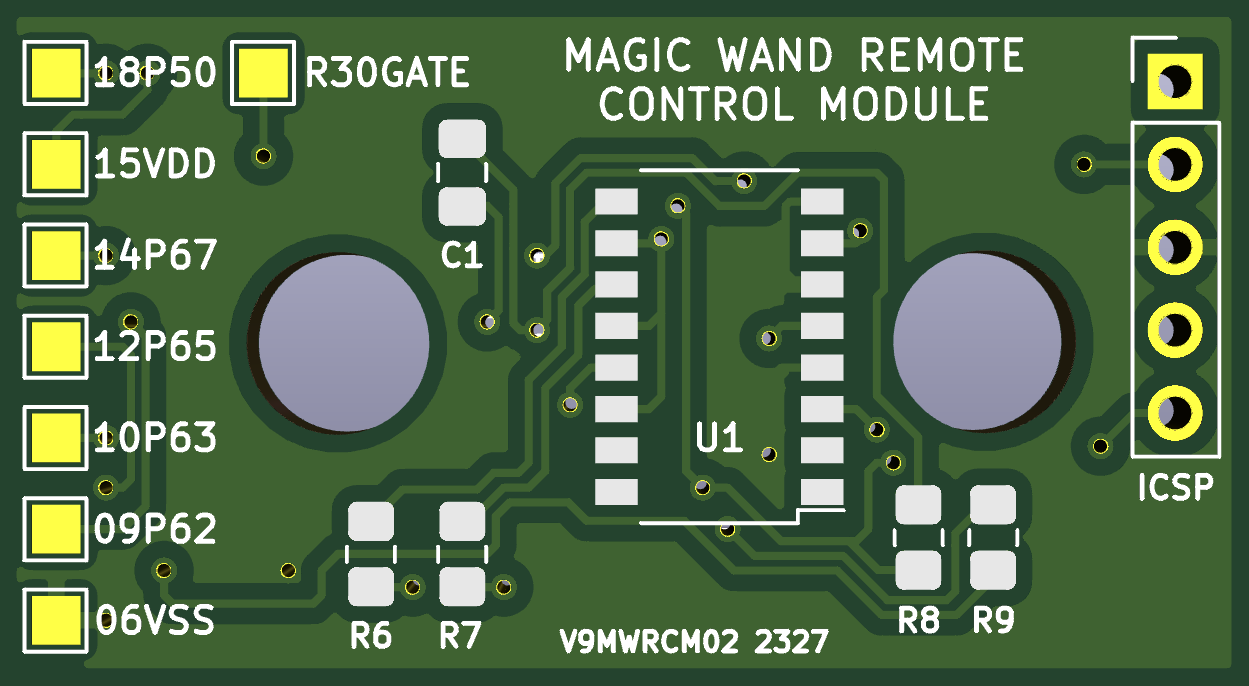
Gerber files for this PCB can be downloaded here v9mwrcm02_2327_gerber.zip
 V9MWRCM02_2327 BOM (All passives are 0805 / 2012 Metric)
 --------------------------------------------------------

 R1  100R (220R is fine too)
 R2  100R (220R is fine too)
 R3  100R (220R is fine too)
 R4  1K
 R5  4.7K
 R6  4.7K
 R7  4.7K
 R8  100R
 R9  1K
 C1  4.7uF
 C2  0.1uF
 U1  TCMT4100
 Q1  2N7002ET7G
 IC1 PIC16F18325-I/SL
 IC2 TSOP4838

 A copy of this listing is included in the Gerber zip file above.