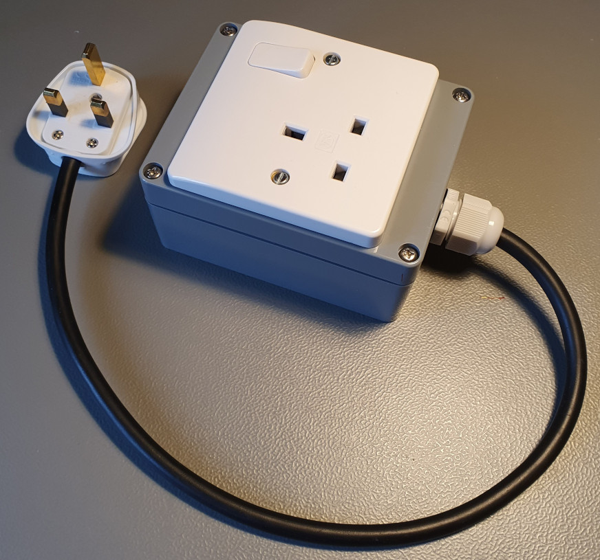
Occasionally I get air locks in the cold feed to my shower pump and the shower becomes unusable. To restore its operation I have to remove the pipe from the end of the pump, allow the air to escape and get water flowing through it into a bucket, then I can reconnect and use the shower again. It doesn't happen very often, and on past occasions it's been caused by the incoming water supply being shut-off temporarily due to works on the water main outside.
The cause of the problem is the water cistern doesn't sit high enough in the loft - it rests on a section of worktop screwed to ceiling joists. A 22mm PEX pipe goes out the side of the water tank running horizontally across - and parallel to - the ceiling joints, before going into an elbow and dropping straight down into the airing cupboard where the shower pump resides.
The pump is a Stuart Turner 'universal' negative-head type, which is necessary so it'll trigger when the shower mixer's operated, despite the inadequate head of water acting on it. So whenever the water cistern empties whilst the shower pump's running, air is drawn into the cold feed, and once the cistern has refilled there's inadequate pressure to shift the air down to the pump.
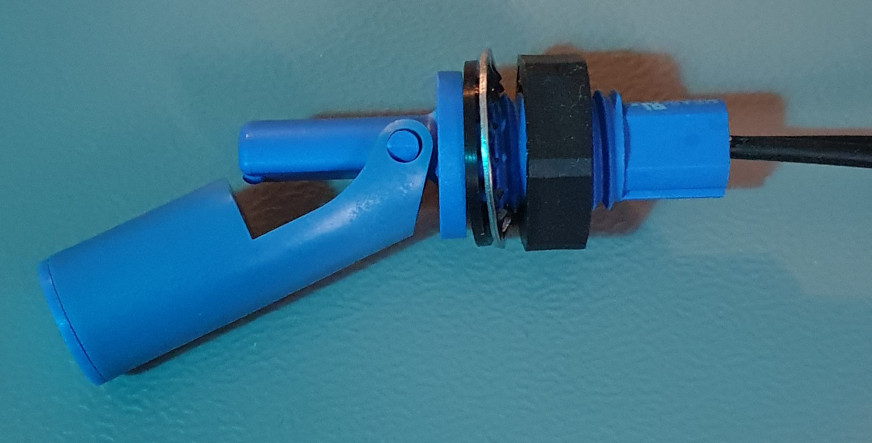
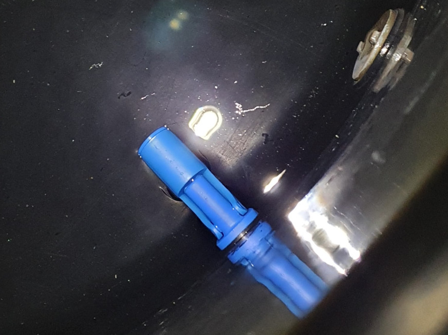
The roof is little more than a metre in height, so even replacing the cistern with a coffin-tank that could be raised higher wouldn't remedy the problem. So naturally I've chosen an electronic solution involving the use of a float-switch installed in the cistern, and the repurposing of one of my Hot Flow Activated Switches (HFAS) to kill the power to the pump if the water level drops too low.

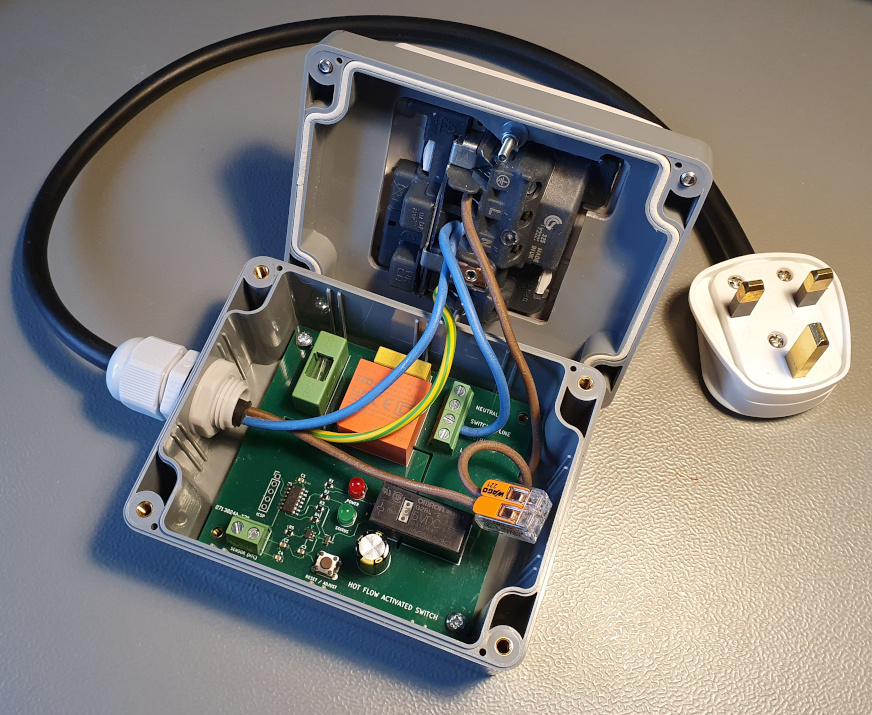
Here I've wired the incoming line and outgoing switched-line to the socket via the normally-closed contacts of the relay - only the normally-open contacts are available on the screw terminal connector, so I've soldered two lengths of 1.5mm2 to the relay terminals on the underside of the PCB.
The sensor input terminals are usually for an NTC thermistor which forms part of a voltage divider feeding an analogue input of the microcontroller. This analogue input is now configured as digital in the code, and triggers an interrupt whenever it's driven high by the closing of the float switch.
Once the input has been triggered there's a short delay to ensure the water level goes slightly lower before power to the pump is shut off. When the pump's turned off the code waits in a loop for the input to change to a low state - i.e. the water level has started to recover. Once this has happened a further delay loop begins, lasting approximately 1.5 minutes, after which time power to the pump is restored. This ensures the water level has risen sufficiently so the pump can't immediately drain the cistern a second time. The delay after an empty or recovering state has been detected prevents a situation where the pump is cycling on and off too frequently, and allows the float-switch to properly reach an absolute position.