
So I decided to create another piece of BDSM furniture, which is based on the now discontinued Headtrap product that Fetters, the British BSDM fetish retailer and manufacturer, used to sell. All images of this product seem to have disappeared from Google, although it can still be found by searching on X / Twitter. I wanted to create something that improved on the original design, incorporating an electronically controlled locking system with digital release timer, operated wirelessly via an infrared remote control.
The dimensions of the original are quite compact, so I decided an additional 100mm in length would make it more accommodating. The original design has the vertical frames bolted to the sides of the base, but I'm bolting them to the top of the base, making it possible to push-fit the padded base boards between them.
The removable top of the Fetters Headtrap product is secured in place with four removable pins, each fitted with a small padlock to prevent removal. In my design the top frame slides onto two brass pegs at the rear, and is secured at the front with an electronically controlled servo actuated brass slide bolt.
There are two wrist restraint mounting pegs that d-rings slip onto. Once the top frame has been secured in place the ends of the restraint pegs are blocked off, making it impossible to remove the d-rings. Ankle restraint is provided by an eye-screw installed in the front base board to which cuffs can be attached using a snap hook.
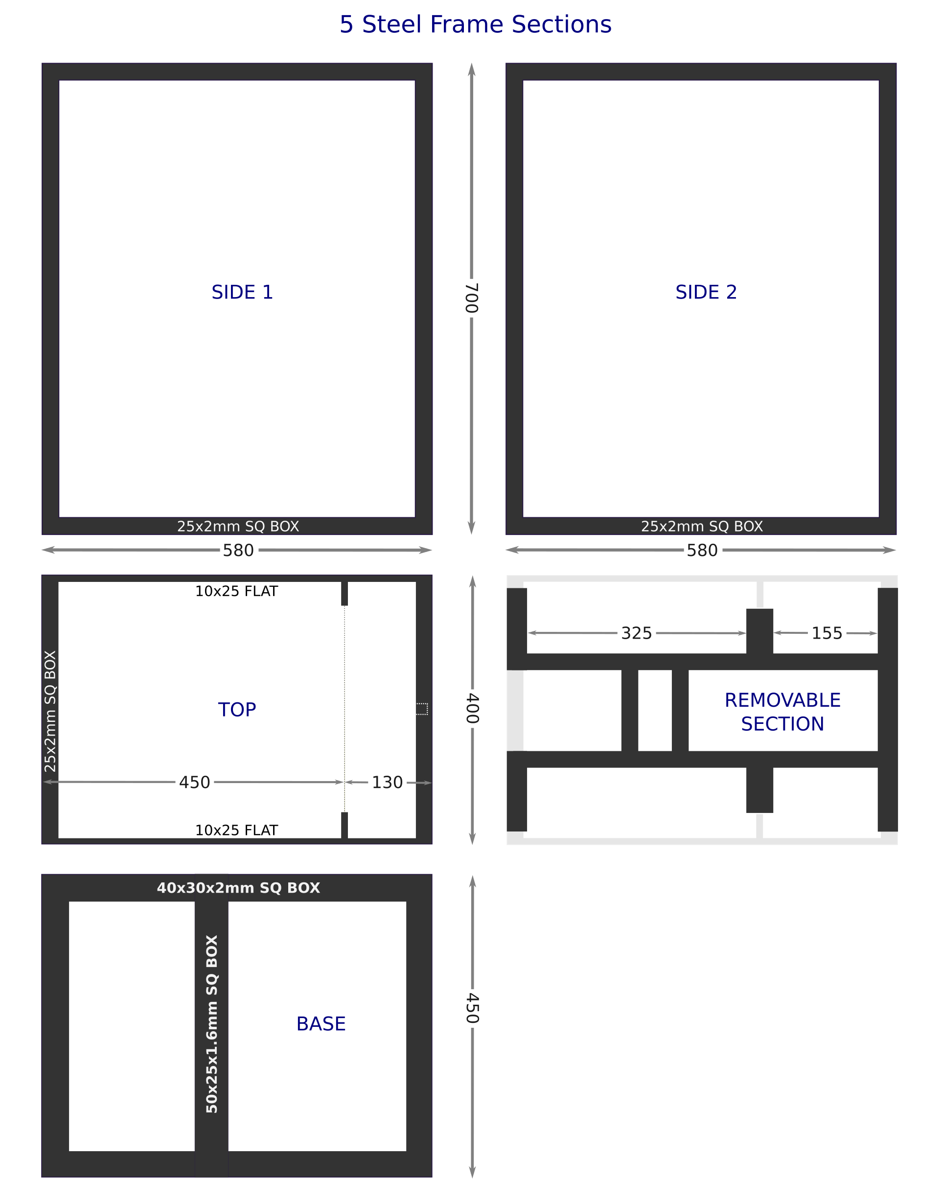

The diagram above shows the five steel parts that form the cage. The removable frame section houses the electronics, batteries, and spring-loaded slide bolt. I'd initially planned on using a mechanical timer, some 555 timers and 4000 series logic to control the servos, but as the project progressed I felt that a microcontroller based system would work better.
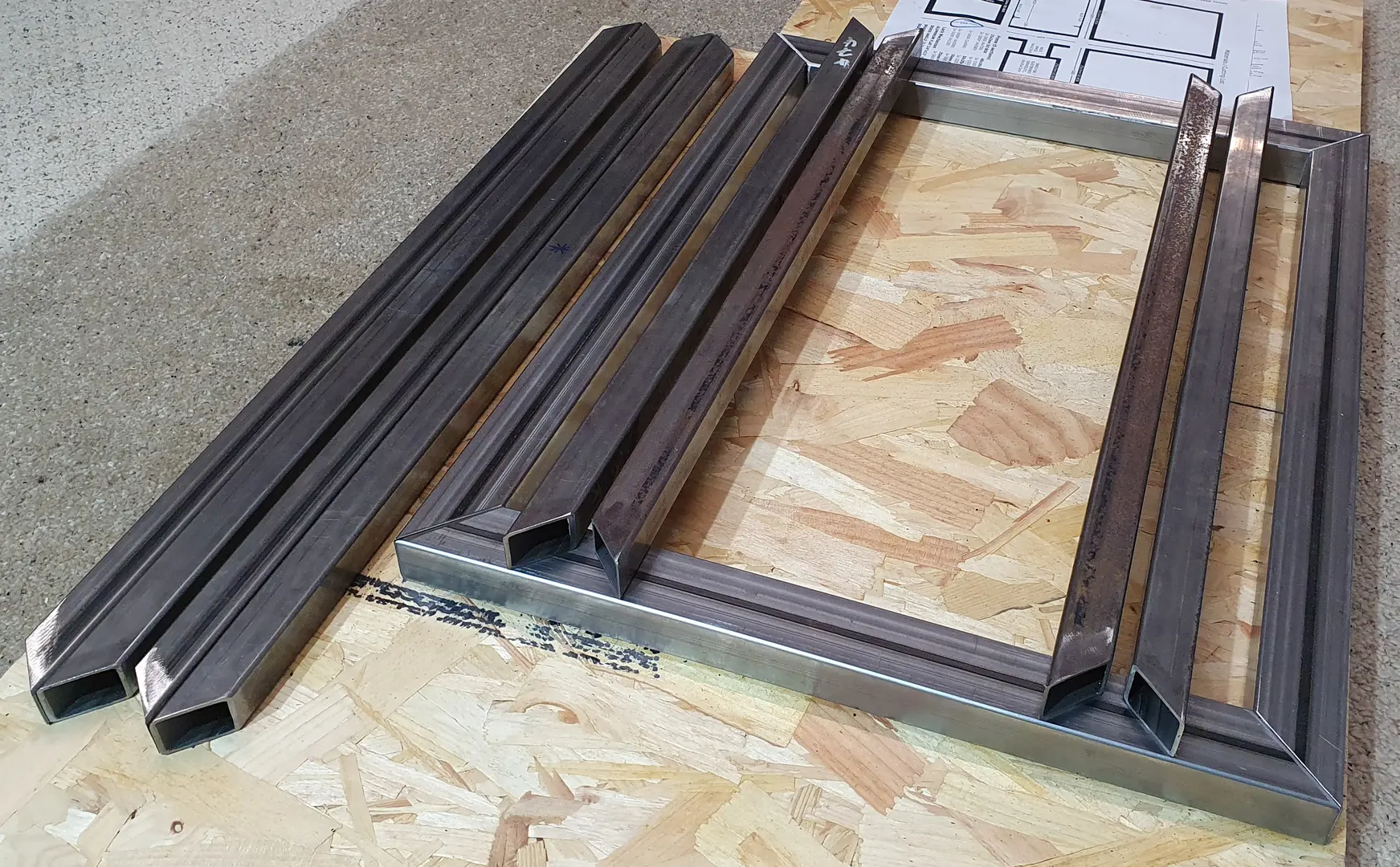
The steel box section for fabricating the cage, cut to length according to the plan, with 45° cuts on the eight pieces that make up the two side frames.
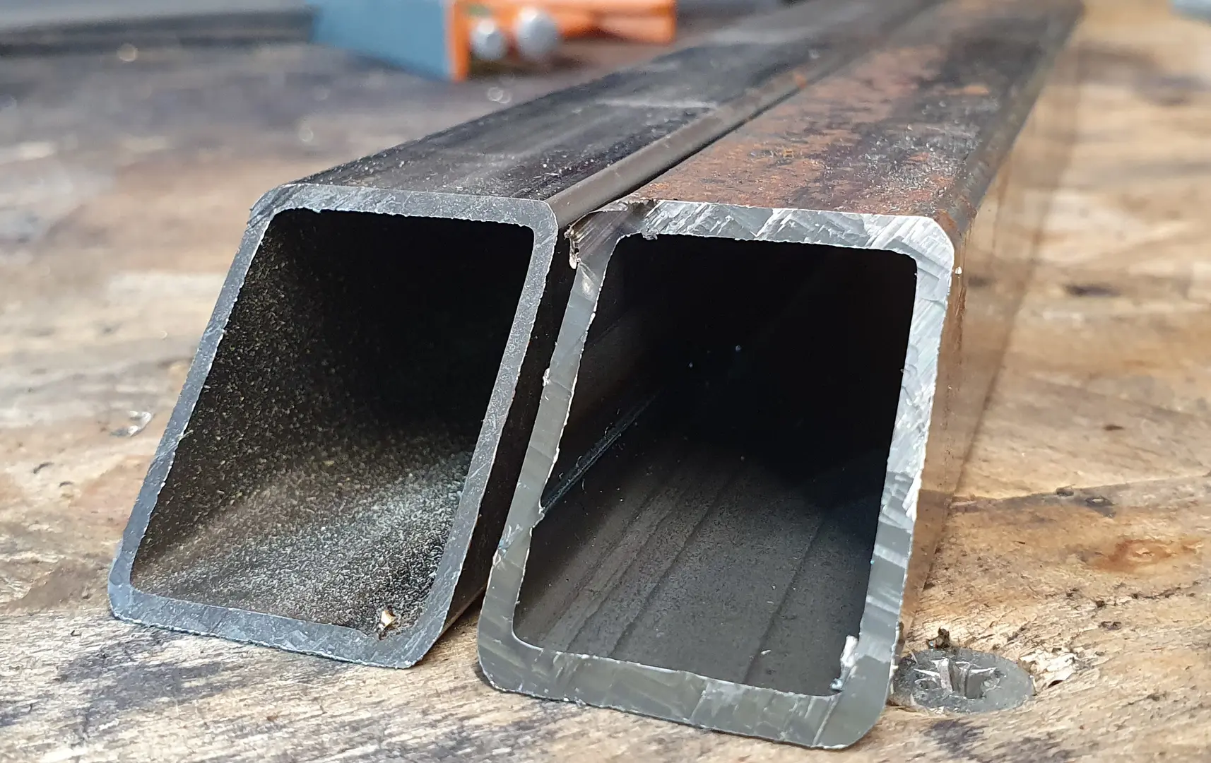
For this project I selected slightly thicker walled steel box section, 2mm instead of the standard 1.6mm, as I figured it would give the frame a more solid weightier feel. There's also less chance of 2mm walled box section bending, either while in transit or actual use.
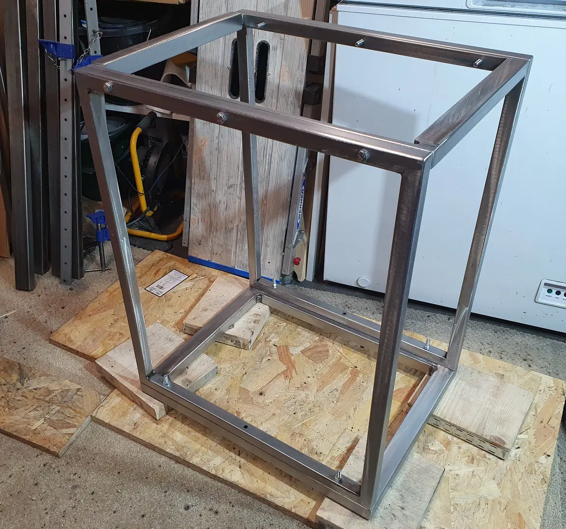
The frame was quick to weld-up, and the dimensions of the completed frame are accurate to well within a millimetre. The holes for the twelve M8 bolts were first centre-punched, drilled and de-burred, then used to mark the position on the mating frame section. I drilled 9mm holes so there was some flexibility to precisely position each part before tightening the bolts and securing it in place.
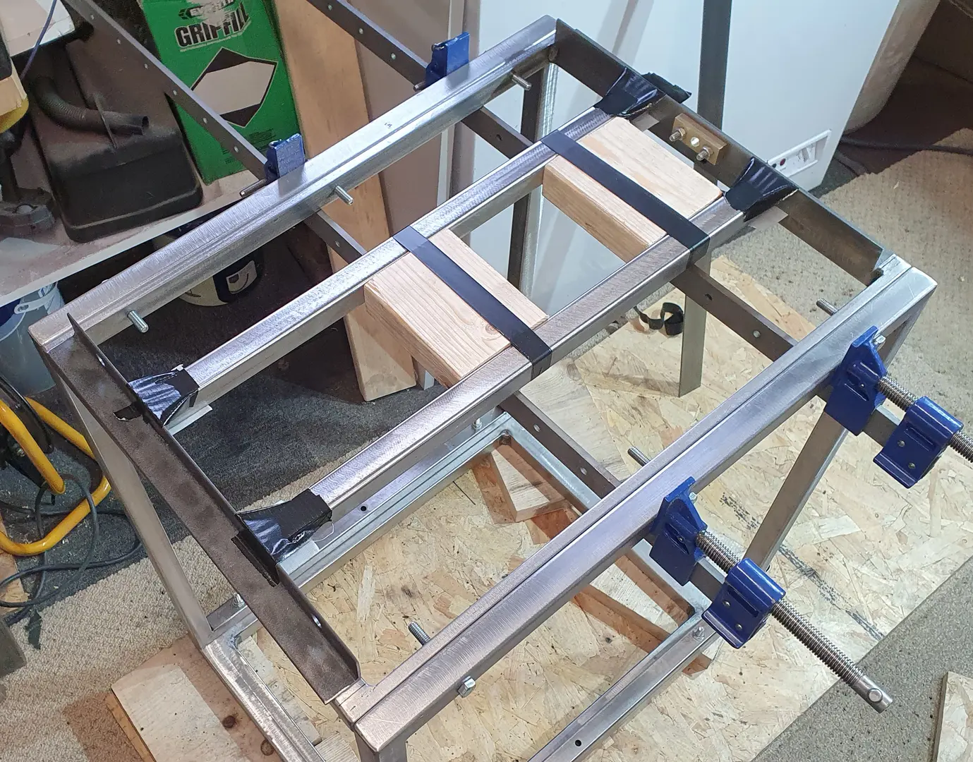
Having modelled it in Inkscape, I was fairly sure the rear angle steel would slide onto the mounting posts, and there was enough space for the front steel to drop down into the frame. I wanted to test-fit prior to welding, so I taped the parts together and attached sash clamps to support the frame.
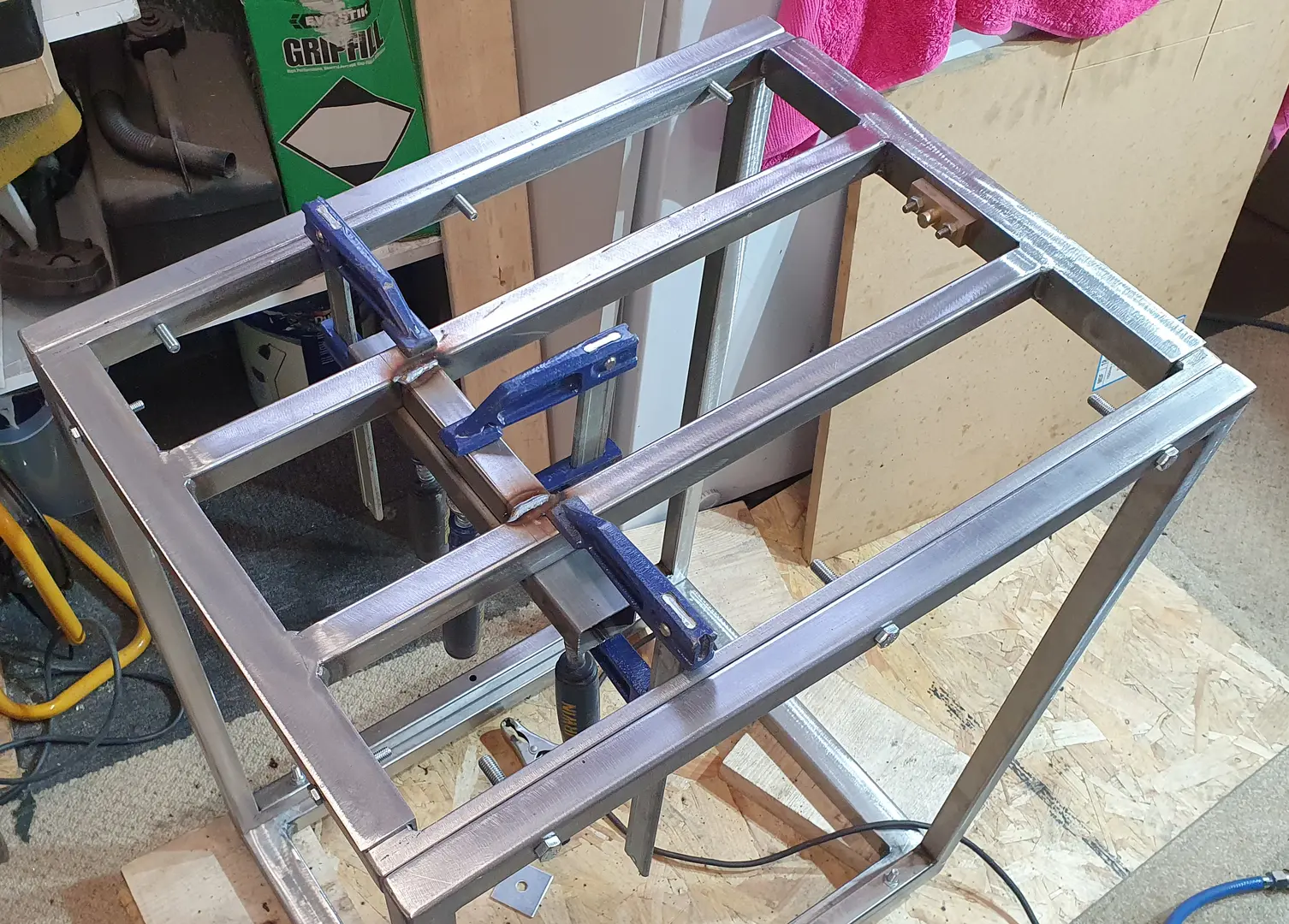
Now everything could be welded together. This was done with both lengths of angle steel positioned in the frame and the connecting columns resting on the sash clamps. Once these four parts were welded, and I had a rigid frame, I could weld in the horizontal sections. The rear section of steel angle, between the side columns of the frame, was cut out last.

The castor wheels are secured to the base frame with M6 socket button screws into steel rivet-nuts. I was going to weld in four triangular pieces of 5mm flat steel, pre-tapped with M6 threads for the fourth castor mounting screw, but decided the three screws were sufficient for fixing each castor.
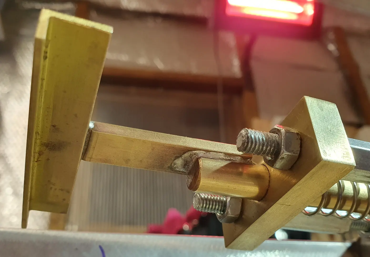
The locking bar and servo horn hanger are made from a combination of flat, angle, and round brass that have been machined down and soldered together. The two brass guide sections, through which the bar slides, are fixed in position using M6 threaded rod and four 30mm connecting nuts. There are two countersunk socket screws mounting the assembly to the powder coated steel frame.
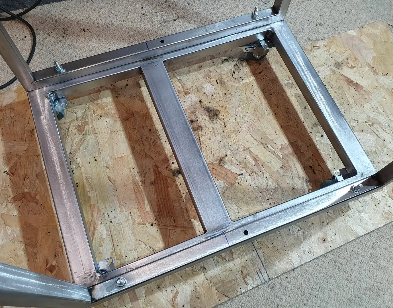
The padded base boards are supported by a cross-member welded in at the point where they meet. This is so each board is well supported around its perimeter, and as the shortest board bears the greatest load, neither should flex or distort.

The padded base boards are made from 9mm OSB, padded with 1" and 2" reconstituted upholstery foam, and wrapped in black vinyl which is glued and stapled to the underside. The boards were made to fit tightly against the side frames so they can be lifted out easily.

The five frame parts dropped off at the powder coaters. This task was taken care of by the friendly and helpful guys at Aurora Powder Coating in Aldershot, who did a fantastic job finishing the parts in satin Traffic Red RAL3020. Check out aurorapowdercoating.co.uk
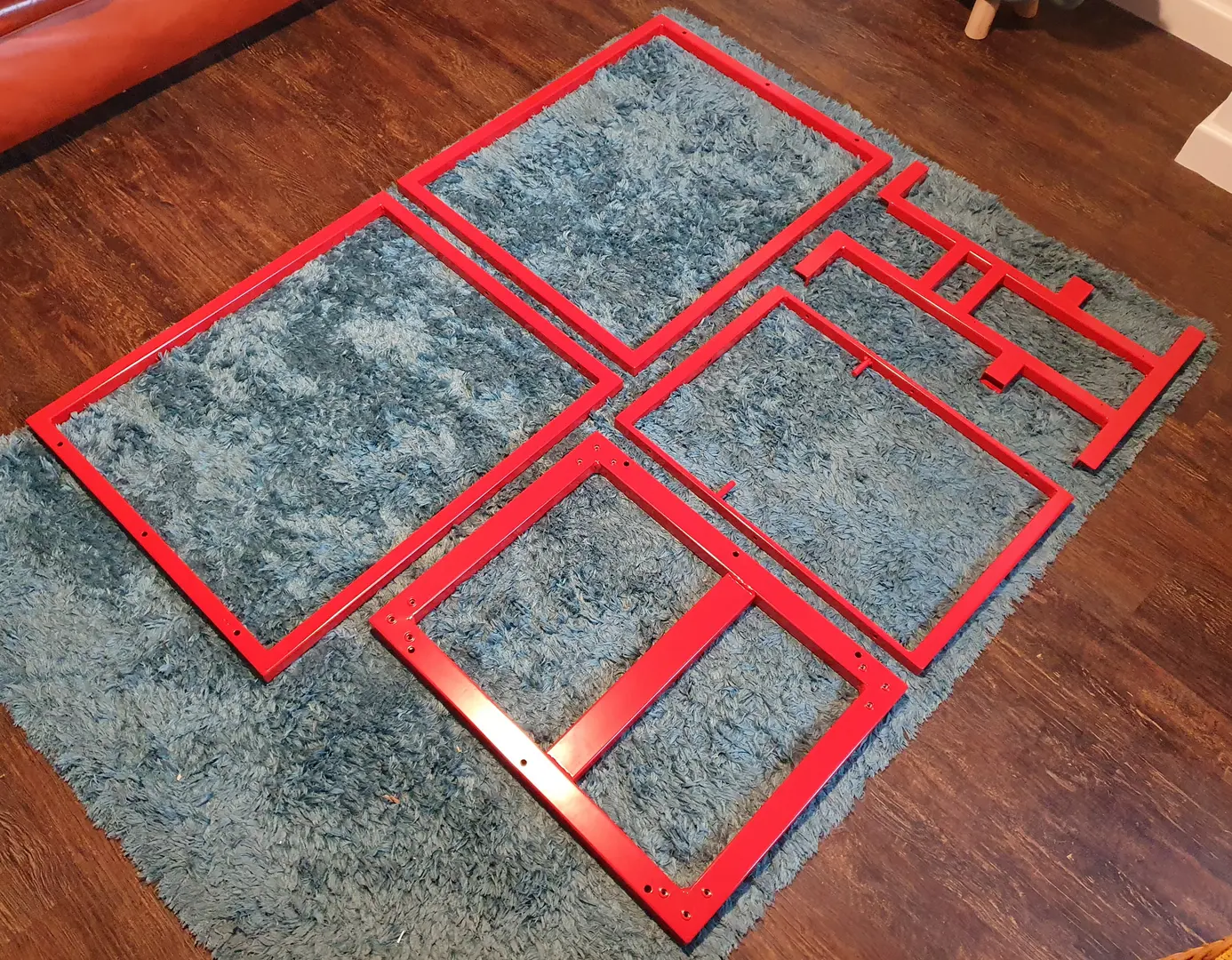
The freshly powder coated parts. I was keen to get it assembled and see the finished cage, especially after all the hours spent designing and fabricating it.

The electronics are mounted on a frosted red acrylic panel. The servo horns below the brass hanger pull it up against the force of the spring, causing the brass bar to retract and allowing removal of the top frame from the cage.
The main circuit board includes a sensory deprivation noise player - a basic MP3 player enabled automatically when locked - to which earphones are connected via the 3.5mm audio jack mounted at the rear of the steel frame; you can see the black and white wires coming from the jack socket.
Powering the electronics is a 6V rechargeable 1.2Ah sealed lead acid battery. There's also an on-board charger, which switches automatically to float charging once the battery is fully charged. This means the AC adaptor can be left connected, permanantly powering the charger, so the battery is always fully charged and the TimeTrap ready for play!

For more details about the electronics used in this project check out the servo lock timer controller article which explains how it all works, with schematics, layout diagrams and the full source code listing!

Trying out my new BDSM furniture for the first time in my rubber suit, Avon FM12 gas mask and Grinders Herald leather boots. The ear phones are connected to the audio jack socket in the left-side of the top frame, for sensory deprivation purposes.
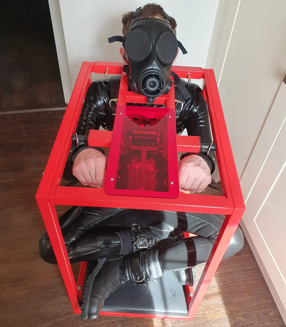
The leather wrist restraints are secured in place until the top frame unlocks and is lifted out. The 8mm steel restraint posts are covered with a short section of silicone tubing, which prevents the metal d-rings clanking against and damaging the powder coated metal inside.
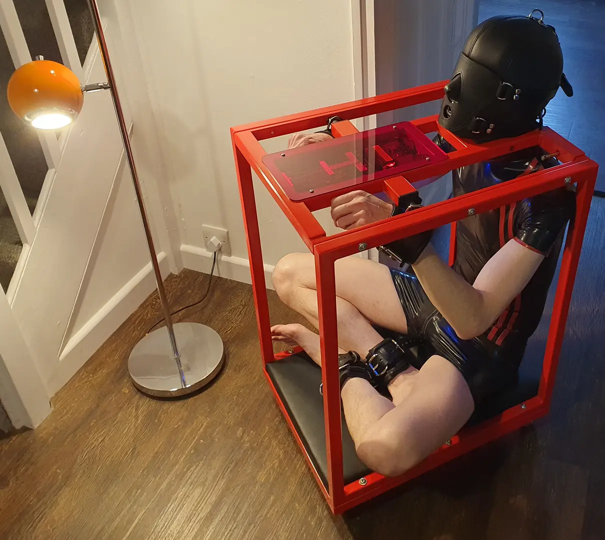
I designed the top frame to work specifically with my Oblivion Hood from Top to Bottom Leathers. Here I'm using my TimeTrap BDSM frame with the leather hood, and also my new rubber shorts and t-shirt from Regulation, with double red stripe to match the traffic red powder coat.
This scene was without the use of sensory deprivation noise, but it clearly shows the position of the 3.5mm earphone jack socket - above and in front of my left shoulder. The cable from the jack socket runs through the inside of the steel tube and enters the electronics compartment through a rubber grommet, where it connects with the MP3 player module.