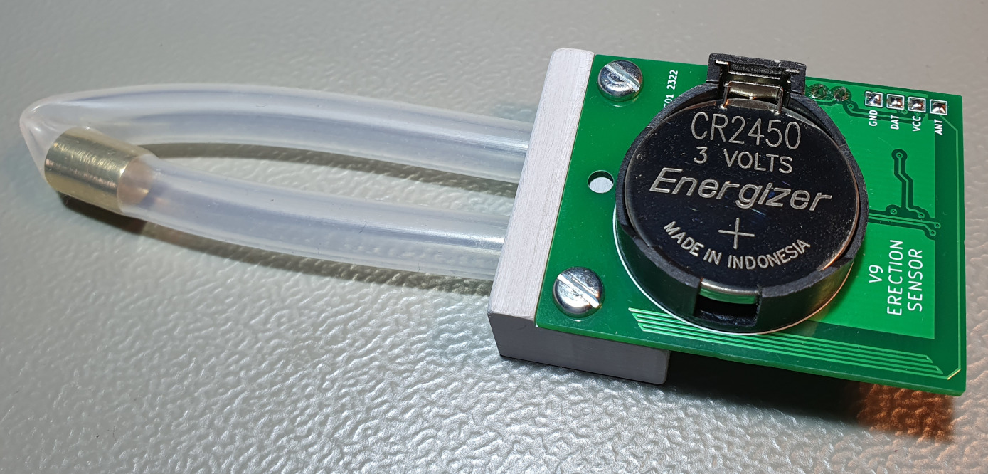
Here is an example of using an MP3V5010DP differential pressure sensor to detect expansion and contraction.
Mechanically, the device simply consists of two lengths of silicone tubing, one of which is sealed with a brass stub and connected to the positive port of the differential pressure sensor. The adjacent tube is open and partially joined to the sealed end of the other. The hoses are secured to the PCB with a suitably machined section of PVC square bar.
When something placed between the two lengths of silicone tube expands, force is applied to the sealed tube increasing its internal pressure, which is detected by the differential pressure sensor. Obviously these changes in pressure are only slight, and therefore an op-amp is used to scale-up the sensor's output voltage to a level that can be seen as a significant change when converted to a digital value by the PIC16LF18325's Analogue to Digital Convertor.
The device is powered using a CR2450 button cell battery. In order to reduce power consumption while in a sleep state an 'LF' designated PIC microcontroller is used, in combination with an N-channel MOSFET which controls power to the op-amp and pressure sensor.
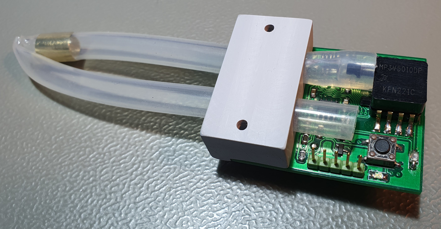
On the top-side of the PCB is a status LED, and push button used to reset and configure the device. There's a 38KHz infrared LED for transmitting status data to a receiving device equipped with a suitably matched infrared sensor - such as a modified Magic Wand massager, for instance!
On the rear of the PCB are four pads for mounting an optional RF transmitter, such as the very reliable QAM-TX2-433 I use in my other projects. This was an experimental addition I included should I wish to control RF devices at some later stage.

Currently the device is programmed to transmit an NEC IR code of 0x19 when expansion is detected, and 0x45 when contraction, from the expanded state, is detected.
These two states are determined by first calculating an average from a set of readings taken from the Analogue to Digital Convertor - consisting of fourteen values, accumulated at two second intervals - and comparing it against an upper and lower threshold value.
An expansion state is set when the average value exceeds the upper threshold, and a contraction state when it drops below the lower threshold. This is very similar to the detection method used in my Hot Flow Activated Switch project.
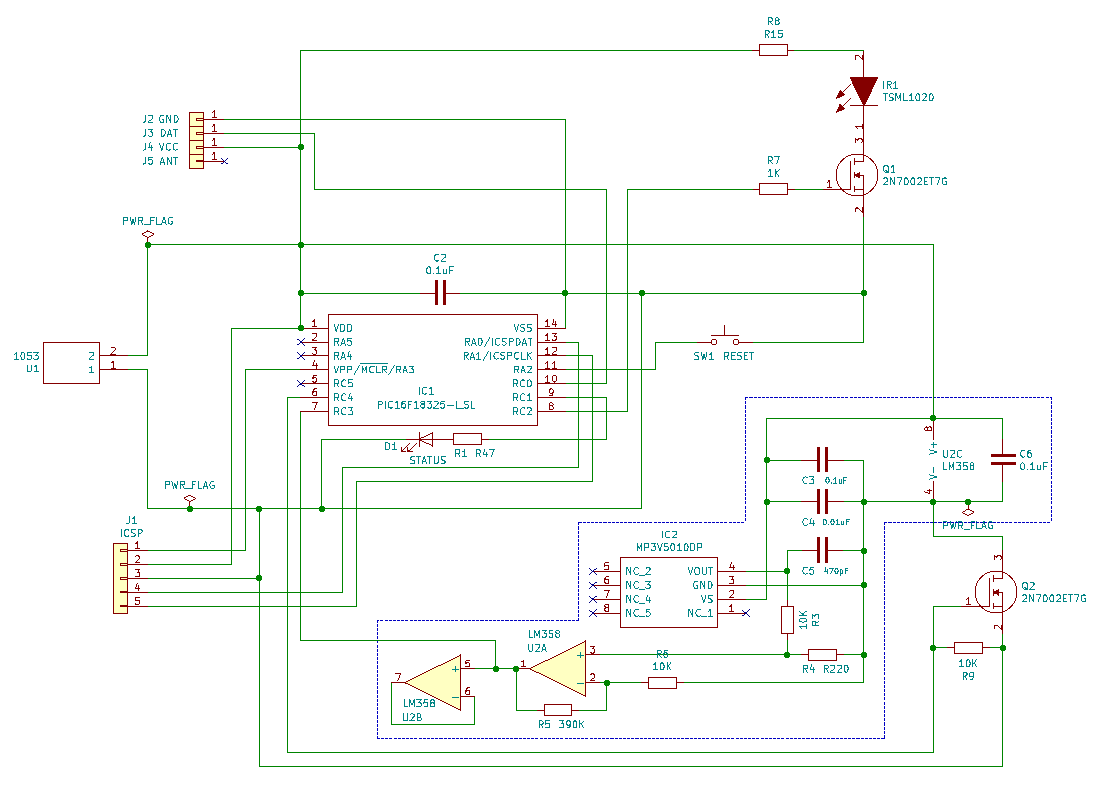
The schematic is fairly self-explanatory. Power to the circuity in the blue-boxed section is controlled by the MOSFET Q2. This is so neither the op-amp or pressure sensor are consuming power when the microcontroller is in a sleep state.
Code listing for use with PIC16LF18325, compiled using MPLAB X IDE V5.15 and XC8 V2.10
/*
* File: pic_erection_detector.c
* Author: paul reynolds ( paul at v9tronics d0t c0m )
*
* Use averaging of the ADC input to detect a sudden change in pressure being
* applied to a MP3V5010DP pressure sensor - for detecting erections obviously!
*
* It's basically a rehash of the HFAS code, but with slower averaging and no
* relay to drive, we're just modulating an IR LED to transmit NEC IR commands.
*
* Created: MAY 2023
*/
// PIC16F18325 Configuration Bit Settings
// 'C' source line config statements
// CONFIG1
#pragma config FEXTOSC = OFF // FEXTOSC External Oscillator mode Selection bits (Oscillator not enabled)
#pragma config RSTOSC = HFINT1 // Power-up default value for COSC bits (HFINTOSC (1MHz))
#pragma config CLKOUTEN = OFF // Clock Out Enable bit (CLKOUT function is disabled; I/O or oscillator function on OSC2)
#pragma config CSWEN = ON // Clock Switch Enable bit (Writing to NOSC and NDIV is allowed)
#pragma config FCMEN = ON // Fail-Safe Clock Monitor Enable (Fail-Safe Clock Monitor is enabled)
// CONFIG2
#pragma config MCLRE = ON // Master Clear Enable bit (MCLR/VPP pin function is MCLR; Weak pull-up enabled)
#pragma config PWRTE = OFF // Power-up Timer Enable bit (PWRT disabled)
#pragma config WDTE = OFF // Watchdog Timer Enable bits (WDT enabled, SWDTEN is ignored)
#pragma config LPBOREN = ON // Low-power BOR enable bit
#pragma config BOREN = SLEEP // Brown-out Reset is enabled while running, disabled in Sleep
#pragma config BORV = LOW // Brown-out Reset Voltage selection bit (Brown-out voltage (Vbor) set to 2.45V)
#pragma config PPS1WAY = ON // PPSLOCK bit One-Way Set Enable bit (The PPSLOCK bit can be cleared and set only once; PPS registers remain locked after one clear/set cycle)
#pragma config STVREN = ON // Stack Overflow/Underflow Reset Enable bit (Stack Overflow or Underflow will cause a Reset)
#pragma config DEBUG = OFF // Debugger enable bit (Background debugger disabled)
// CONFIG3
#pragma config WRT = OFF // User NVM self-write protection bits (Write protection off)
#pragma config LVP = ON // Low Voltage Programming Enable bit (Low Voltage programming enabled. MCLR/VPP pin function is MCLR. MCLRE configuration bit is ignored.)
// CONFIG4
#pragma config CP = OFF // User NVM Program Memory Code Protection bit (User NVM code protection disabled)
#pragma config CPD = OFF // Data NVM Memory Code Protection bit (Data NVM code protection disabled)
#define _XTAL_FREQ 4000000
#include <xc.h>
#include <stdio.h>
#include <stdlib.h>
#include <string.h>
/*
* PIC16F18325
* [+++] [---]
* [RA5] [RA0]
* [RA4] [RA1]
* [RA3] [RA2]
* [RC5] [RC0]
* [RC4] [RC1]
* [RC3] [RC2]
*
* O RA0 > UART_TX_OUT (FOR DEBUGGING)
* I RA2 > SETUP BUTTON (INT)
* O RC1 > STATUS LED
* O RC5 > OUTPUT PIN (N/C)
* O RC4 > 2N7002: POWER TO LM358 / MP3V5010DP
* I RC3 > AN3: SIGNAL FROM LM358 / MP3V5010DP
*/
#define SET_BUTTON RA2
#define STATUS_LED RC1
#define SENSOR_PWR RC4
#define OUTPUT_PIN RC5
#define IR_38KHZ CCP1CONbits.CCP1EN
#define _ON_ 1
#define _OFF_ 0
#define START 1
#define STOP 0
#define TRUE 1
#define FALSE 0
#define PRESSED 0
int STORE_ADC_V;
int CURRENT_VAL;
int THE_AVERAGE;
int CYCLE_COUNT;
int counter_a = 0;
int counter_b = 0;
int counter_c = 0;
int avg_samples[14];
char serial_text[75];
int INITIALISE = 1;
int ERECTION = 0;
// these parameters will be loaded from EEPROM and can be adjusted by the user
// we're just setting them up here with the defaults so they can be loaded into
// the EEPROM when restoring default values.
int PARAM_DELAY_M;
int PARAM_TRIGGER;
int PARAM_RESTORE;
int PARAM_AVG_DUR;
int PARAM_VERBOSE;
//
// send magic wand remote control commands
//
unsigned int magic_wand_one = 0x45; // turn on, lowest intensity
unsigned int magic_wand_zero = 0x19; // turn off
void send_ir( int command, int tx_times ){
int command_tmp;
// prevent our transmission from being interrupted
INTCONbits.GIE = FALSE;
INTCONbits.PEIE = FALSE;
T0CON0bits.T0EN = FALSE;
// NEC remote address, and inverted-address
unsigned int address_one = 0x00;
unsigned int address_two = 0xFF;
TMR2ON = TRUE; // enable Timer2
for( int x = 0; x < tx_times; x++ ){
IR_38KHZ = TRUE; __delay_ms(9); // AGC pulse
IR_38KHZ = !IR_38KHZ; __delay_us(4500); // long pause
IR_38KHZ = !IR_38KHZ; __delay_us(550);
for( int yy = 0; yy < 4; yy++ ){
switch(yy){
case 1: command_tmp = address_one; // byte1: address
break;
case 2: command_tmp = address_two; // byte2: inverted-address
break;
case 3: command_tmp = command; // byte3: command
break;
case 4: command_tmp = ~command; // byte4: inverted-command
break;
}
for( int y = 0; y < 8; y++ ){
IR_38KHZ = !IR_38KHZ;
if( (command_tmp & 1) == 1 ){
__delay_us(1650);
}else{
__delay_us(550);
}
IR_38KHZ = !IR_38KHZ;
__delay_us(550);
command_tmp >>= 1; // shift one bit right
}
}
IR_38KHZ = FALSE; // disable CCP1EN (Capture Compare PWM) output
// pause between repeats - ideally 42 milliseconds to be valid NEC IR
for( int yy = 0; yy < 42; yy++ ){ __delay_ms(1); }
}
TMR2ON = FALSE;
// no longer transmitting, so interrupts are fine now
INTCONbits.GIE = TRUE;
INTCONbits.PEIE = TRUE;
T0CON0bits.T0EN = TRUE;
}
//
// for writing to the serial port when debugging
//
void tx_string( char * data_arr ){
unsigned int posi = 0;
unsigned int leng = strlen( data_arr );
while( posi < leng ){
while(!TRMT);
TXREG = data_arr[posi];
while(!TRMT);
__delay_ms(2);
posi ++;
}
}
//
// read value from analogue to digital converter
//
int get_adc_value(){
ADCON0bits.GO = 1; // start the conversion
while( ADCON0bits.GO == 1 ){ ; }; // wait for the conversion to end
int adc_value = (ADRESH<<8)+ADRESL; // combine the 10 bits of the conversion
return adc_value;
}
//
// add a sample to our array of fourteen samples
//
void add_a_sample( int *arr_values, int new_value ){
// shift values down one position
for(int i=14; i>0; i--){
arr_values[i] = arr_values[i-1];
}
// add new value to the beginning
arr_values[0] = new_value;
}
//
// calculate an average from our fourteen samples
//
int get_average( int *arr_values ){
int total = 0;
int number_of_numbers = 0;
for(int i=0; i<15; i++){
total = total + arr_values[i];
number_of_numbers++;
}
int result = total / number_of_numbers;
return result;
}
//
// initialise - called on startup and when pressing the button
//
void initialise( int *arr_values ){
// fill array with the current value
for(int i=0; i<14; i++){
arr_values[i] = CURRENT_VAL;
}
THE_AVERAGE = CURRENT_VAL;
STORE_ADC_V = TRUE; // flag to call average refresh below
OUTPUT_PIN = _OFF_;
__delay_ms(250);
}
//
// flash our status LED as required
//
void flash_led( int speed, int times ){
for(int i=1; i<=times; i++){
STATUS_LED = _ON_;
for(int y=0; y<=speed; y++){ __delay_ms(10); }
STATUS_LED = _OFF_;
for(int y=0; y<=speed; y++){ __delay_ms(10); }
}
}
//
// called to put PIC into sleep state
//
void pic_sleep(){
// shut down the serial port
SPEN = 0;
TXEN = 0;
// turn off power to the sensor
SENSOR_PWR = FALSE;
// disable ADC - otherwise this consumes power while in sleep
ADCON0bits.ADON = 0;
// indicate we're going to sleep
flash_led( 10, 2 );
// turn off high frequency oscillator
OSCENbits.HFOEN = 0;
asm("SLEEP");
}
//
// called after PIC has been woken
//
void pic_awake(){
OSCENbits.HFOEN = 1;
// enable serial port
SPEN = 1;
TXEN = 1;
// power to the sensor...
SENSOR_PWR = TRUE;
// and ADC
ADCON0bits.ADON = 1;
// flash once to indicate we're awake!
flash_led( 10, 1 );
}
//
// interrupt service routine
//
void __interrupt () my_isr_routine (void){
// a button press triggers INT
if( PIR0bits.INTF == 1 ){
INITIALISE = TRUE; // flag to call initialise routine
PIR0bits.INTF = 0; // clear interrupt flag
}
// timer zero adds a sample every x seconds
if( PIR0bits.TMR0IF == 1 ){
// add a sample PARAM_AVG_DUR * (15 = 1 second)
if( counter_a > (PARAM_AVG_DUR * 15) ){
STORE_ADC_V = TRUE;
counter_a = 0;
}
if( counter_a > 15 ){
// rapidly flash LED when an erection has been detected
if( ERECTION == TRUE ){
STATUS_LED = ~STATUS_LED;
}
}
counter_a ++;
PIR0bits.TMR0IF = 0; // clear interrupt flag
}
// IOC3/RA3
if( IOCAF3 == 1 ){
IOCAF3 = 0;
}
// IOC3/RA2
if( IOCAFbits.IOCAF2 == 1 ){
IOCAFbits.IOCAF2 = 0;
IOCANbits.IOCAN2 = 0;
PIR0bits.IOCIF = 0;
}
}
int main(){
// OSCILLATOR @ 4MHz
OSCCON1bits.NOSC = 0b110; // HFINTOSC (1MHz)
OSCCON1bits.NDIV = 0b0000; // divide by 1
OSCFRQbits.HFFRQ = 0b0011; // 4MHz (1MHz = 0b0000)
OSCENbits.HFOEN = 1; // enable high-frequency oscillator
CPUDOZEbits.IDLEN = 0; // sleep instruction places the device into full-sleep mode
VREGCONbits.VREGPM = 1; // low-power sleep mode enabled in sleep
// PIN SETUP
TRISA = 0b00000100; // outputs, except RA2 button
ANSELA = 0b00000000; // all digital pins
TRISC = 0b00001000; // outputs, except RC3 2N7002 to power MP3V5010DP / LM358
ANSELC = 0b00001000; // all digital pins, except RC3/ANC3 MP3V5010DP / LM358
// WEAK PULL UPS
WPUAbits.WPUA2 = 1; // enable weak pull up on RA2 (BTN)
WPUAbits.WPUA3 = 1; // enable weak pull up on RA3 (MCLR)
// UART CONFIG
SYNC = 0; // disable for asynchronous EUART
SPEN = 0; // enables the EUSART and sets TX/CK I/O pin as output
TXEN = 0; // enables transmitter
RA0PPS = 0b10100; // peripheral pin setup - UART TX is on RA0 (ICSP:PIN4)
CREN = 0; // enables receiver
TX9 = 0; // set to 8bit transmit
RX9 = 0; // set to 8bit receive
// UART BAUD RATE
BRGH = 1; // baud rate generator - high baud rate
BRG16 = 1; // baud rate generator - 8 bit operation
SPBRG = 103; // baud rate generator - 9600@4MHz
SENDB = 1; // send break character
// INTERRUPT SETUP
INTCONbits.INTEDG = 0; // interrupt on INT falling edge
PIR0bits.INTF = 0; // reset INT interrupt flag
PIE0bits.INTE = 1; // /./enable INT interrupt
PIE0bits.IOCIE = 1; // enable IOC interrupt
IOCANbits.IOCAN2 = 1; // enable IOC negative edge detection on RA2
INTCONbits.GIE = 1; // global interrupt enable
INTCONbits.PEIE = 1; // peripheral interrupts enable
// ADC SETUP
ADCON1bits.ADFM = 1; // ADC result is right justified
ADCON1bits.ADNREF = 0; // negative reference to ground
ADCON1bits.ADPREF = 0b00; // V REF + is connected to VDD
ADCON1bits.ADCS = 0b101; // Fosc/2 is the conversion clock
ADCON0bits.CHS = 0b010011; // select analog input, ANC3/RC3
ADCON0bits.ADON = 0; // turn on adc
// TMR0 SETUP
T0CON0bits.T0EN = 1; // timer 0 enabled
T0CON0bits.T016BIT = 0; // an 8 bit timer
T0CON0bits.T0OUTPS = 0; // 1:1 post-scaler
T0CON1bits.T0CS = 0b010; // ? Fosc / 4 ????
T0CON1bits.T0CKPS = 0b1000; // pre-scaler 1:256
T0ASYNC = 0;
TMR0L = 0;
TMR0IF = 0; // clear the Timer 0 interrupt flag
TMR0 = 0; // load a value of 0 into the timer
TMR0IE = 1; // enable the Timer 0 interrupt
// CCP1 PWM configuration - for modulating our IR LED at 38kHz
RC2PPS = 0b01100; // RC2 source is CCP1
PR2 = 25; // 76.92 kHz @ 8MHz
CCP1CONbits.CCP1MODE = 0b1111; // PWM mode
CCP1CONbits.CCP1EN = 0; // turn CCP1 on/off
CCPR1L = 48; // 53% duty cycle - make 50% at some point
CCPR1H = 0;
CCPTMRSbits.C1TSEL = 0b01; // CCP1 Capture, Compare and PWM mode on Timer2
// TMR2 configuration
T2CONbits.T2CKPS = 0b00; // 1:1 prescaler
T2CONbits.T2OUTPS = 0b0000; // 1:1 postscaler
T2CONbits.TMR2ON = 0; // turn timer2 off - enable when required
TMR2IE = 0;
TMR2IF = 0;
//
// default parameters
//
PARAM_DELAY_M = 1; // just one minute
PARAM_TRIGGER = 10; // trigger when cur_value is x points above average
PARAM_RESTORE = 8; // restore when cur_value is x points below average
PARAM_AVG_DUR = 2; // take a sample for averaging every x seconds
PARAM_VERBOSE = 1; // transmit debug information via serial port
//
// if EEPROM hasn't been written to yet, or we've powered-on
// with the button pressed, write the default parameters and restart
//
if( eeprom_read( 0x10 ) != 5 || SET_BUTTON == 0 ){
for( int x = 0; x <= 5; x++ ){
STATUS_LED = ~STATUS_LED;
__delay_ms(200);
}
STATUS_LED = 0;
flash_led(200,5);
eeprom_write( 0x10, 5 );
eeprom_write( 0x02, PARAM_DELAY_M );
eeprom_write( 0x03, PARAM_TRIGGER );
eeprom_write( 0x04, PARAM_RESTORE );
eeprom_write( 0x06, PARAM_AVG_DUR );
eeprom_write( 0x07, PARAM_VERBOSE );
__delay_ms(500);
RESET();
}
//
// initialise parameters stored in EEPROM
//
PARAM_DELAY_M = eeprom_read( 0x02 );
PARAM_TRIGGER = eeprom_read( 0x03 );
PARAM_RESTORE = eeprom_read( 0x04 );
PARAM_AVG_DUR = eeprom_read( 0x06 );
PARAM_VERBOSE = eeprom_read( 0x07 );
//
// variables used when pressing the button / adjusting parameters
//
int btn_press_counter = 0;
int btn_press = 0;
int btn_abort_counter = 0;
//
// only enable the serial port if it's required
//
if( PARAM_VERBOSE ){
SPEN = 1; // enables the EUSART and sets TX/CK I/O pin as output
TXEN = 1; // enables transmitter
}
//
// once powered on go to sleep
//
pic_sleep();
pic_awake();
while(1){
CURRENT_VAL = get_adc_value();
//
// add a new sample for averaging - called by timer-zero interrupt
//
if( STORE_ADC_V == TRUE ){
add_a_sample( avg_samples, CURRENT_VAL );
THE_AVERAGE = get_average( avg_samples );
STORE_ADC_V = FALSE;
}
//
// send values and parameters to serial port - if enabled
//
if( PARAM_VERBOSE == 1 ){
sprintf( serial_text, " AVG %d CUR %d ERECT %d CYCLE %d [T+%d R-%d AVG%d]\r\n",
THE_AVERAGE, CURRENT_VAL, ERECTION, CYCLE_COUNT, PARAM_TRIGGER, PARAM_RESTORE, PARAM_AVG_DUR );
tx_string( serial_text );
}
//
// reset averaging etc.
//
if( INITIALISE ){
initialise( avg_samples );
INITIALISE = 0;
}
// if the ADC input has RISEN SIGNIFICANTLY above average then
// turn ON the output, but not if it's already ON
if ( ( CURRENT_VAL - PARAM_TRIGGER ) > THE_AVERAGE ){
/////////////////////////////////////////
/// ERECTION DETECTED / TURN WAND OFF ///
/////////////////////////////////////////
if( OUTPUT_PIN == _OFF_ ){
OUTPUT_PIN = _ON_;
ERECTION = TRUE;
if( PARAM_VERBOSE ){
sprintf( serial_text, " TURNING OFF IN... ");
tx_string( serial_text );
}
// on every even/other COUNT_CYCLE turn wand off after 4 seconds
if( CYCLE_COUNT % 2 == 0){
// 4 sec delay / flash LED
for(int i=1; i<=4; i++){
STATUS_LED = _ON_;
__delay_ms(500);
STATUS_LED = _OFF_;
__delay_ms(500);
if( PARAM_VERBOSE ){
sprintf( serial_text, "%d ", i );
tx_string( serial_text );
}
// escape loop if the button has been pressed
if( INITIALISE ){ i = 1000; }
}
}
if( PARAM_VERBOSE ){
sprintf( serial_text, " NOW! \r\n");
tx_string( serial_text );
}
send_ir( magic_wand_zero, 10 ); // turn off the MW, TX*10
}
}
// if the ADC input goes SIGNIFICANTLY BELOW AVERAGE then
// turn OFF the output, but not if it's already OFF
if( ( CURRENT_VAL + PARAM_RESTORE ) < THE_AVERAGE ){
////////////////////////////////////
/// ERECTION LOST / TURN WAND ON ///
////////////////////////////////////
if( OUTPUT_PIN == _ON_ ){
OUTPUT_PIN = _OFF_;
ERECTION = FALSE;
if( PARAM_VERBOSE ){
sprintf( serial_text, " TURNING ON IN... ");
tx_string( serial_text );
}
// delay gradually gets longer with every on/off cycle
for(int i=1; i<=(10+CYCLE_COUNT)*2; i++){
STATUS_LED = _ON_;
__delay_ms(500);
STATUS_LED = _OFF_;
__delay_ms(500);
if( PARAM_VERBOSE ){
sprintf( serial_text, "%d ", i );
tx_string( serial_text );
}
// escape loop if the button has been pressed
if( INITIALISE ){ i = 1000; }
}
if( PARAM_VERBOSE ){
sprintf( serial_text, " NOW! \r\n");
tx_string( serial_text );
}
send_ir( magic_wand_one, 3 ); // turns on the MW, TX*3
CYCLE_COUNT ++; // increment cycles since reset
}
}
__delay_ms(250);
//
// respond to button presses
//
while( SET_BUTTON == PRESSED ){
// one press sends an off command and resets averaging
STATUS_LED = _OFF_;
ERECTION = FALSE;
CYCLE_COUNT = 0;
send_ir( magic_wand_one, 3 ); // turns on the MW
initialise( avg_samples );
if( PARAM_VERBOSE ){
sprintf( serial_text, " 1) RESET! \r\n");
tx_string( serial_text );
}
flash_led( 300, 1 ); // once to confirm option #1
btn_press = 1;
btn_press_counter = 0;
// select an option by holding the button and counting flashes
while( SET_BUTTON == PRESSED ){
btn_press_counter ++;
if( btn_press_counter > 10000 ){
flash_led( 300, 1 );
btn_press ++;
btn_press_counter = 0;
}
}
while( btn_press > 0 ){
if( btn_press == 2 ){
// enter sleep state...
if( PARAM_VERBOSE ){
sprintf( serial_text, " 2) SLEEP! \r\n");
tx_string( serial_text );
}
flash_led( 300, 2 ); // twice to confirm option #2
pic_sleep();
pic_awake();
}
if( btn_press == 3 ){
// does nothing as yet
if( PARAM_VERBOSE ){
sprintf( serial_text, " 3) DOES NOTHING YET! \r\n");
tx_string( serial_text );
}
flash_led( 300, 3 ); // thrice to confirm option #3
}
//
// Later we'll add options here for changing operating parameters
//
btn_press = 0;
break;
}
}
//end while
}
// end main
}