

This is an improved and more compact version of an earlier IR receiver / decoder project. This design can transmit and receive NEC infrared data, and can be connected via USB-C to a host system. It can also be powered from a USB-C power bank for standalone use as a simple NEC infrared receiver / decoder.

Showing the data sent from the Auraglow infrared remote control. When first powered the module starts in receive and decode mode. Whenever any data is received it's shown immediately on the LCD display.

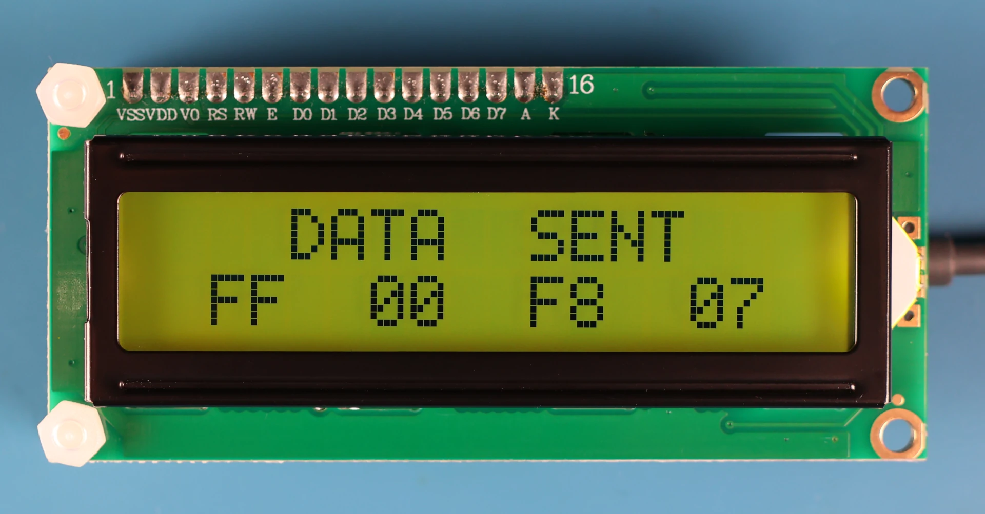
I use GTKTerm on my Ubuntu system to communicate with the module via its USB-C interface. Transmission of infrared data is simply a matter of using a serial terminal to send the four bytes making up an NEC data frame, plus a final 'number of transmits' byte to initiate the infrared transmission, once the transmission has completed the bytes sent are shown on the LCD display, as per the image below.
Having started work on the initial schematic it soon became apparent that a 74HC595 shift register could be used to control the 1602 LCD display, which meant I could use my favourite PIC16F18325 microcontroller instead of switching to a larger PIC18F chip - probably another PIC18F26K22! The handy little 16F18325 even has the same footprint and pin arrangement as the 16F1455 used in the earlier infrared decoder project.

The project was initially built up on a breadboard, and code written to get the basic functionality working. This initial code allowed data from an NEC infrared remote control to be received, decoded, and displayed on screen, plus transmitted to a terminal application running on a PC connected via a USB-to-serial adaptor cable. The bytes of data could then be pasted back into the terminal for transmission to a nearby device - an old Toshiba TV, used as the monitor for the BBC Microcomputer, set up on an adjacent desk.
This connectivity allows the device to be controlled using any programming language with libaries for communicating with a serial port. There are code examples below written in C which demonstrate transmission of infrared data, and control of the attached 1602 LCD display.
The FT232RNL Serial-to-USB chip is only avilable as an SSOP-28 surface mount package, so extra care was taken during the PCB design phase, and when reading the datasheet for this part. The USB interfacing aspect was replicated exactly from one of the application examples in the datasheet, right down to the suggested MI0805K400R-10 ferrite bead.

There are some specific requirements when drawing power from a USB port that needed some consideration. For instance, a connected device must not draw more than 100ma when initially powered, and when the host system enters a suspend state the device should draw less than 2.5ma.
This means there would need to be communication between the FT232 and PIC16F for putting the latter in a low power state, having first turned off the LCD display and its backlight. This is achieved using the control line between FT232:CBUS3 and PIC16F:RC2 (PWR_ENABLE), the code running on the PIC continuously monitors this line and enters sleep when active (high). Interrupt on Change - falling edge detection on RC2 - is used to wake the PIC from its sleep state when the USB host resumes from its suspend state.
In the inital design the LCD display was simply a way of showing the infrared data that had been received when used as a stand-alone device. It soon became apparent that this module could act as an interface between a USB host and 1602 LCD display, allowing the host to address and write data to the display directly.
Transmission of infrared data is achieved by simply writing to the device the four bytes making up the NEC data (address, inverted address, data, inverted data) followed by a 'number of transmissions' byte. This final byte dictates how many times the complete frame of NEC data will be sent, and also initiates the transmission. This five-byte sequence is all that's required for sending infrared data. The first four bytes could be anything from 0 to 255 decimal, but the final byte should be a value lower than ten, in fact two or three repeat transmissions is plenty. So I decided to use this fifth byte as a way of entering a special mode for addressing the LCD display.
The LCD display has two registers to which data can be written: The 'instruction register', selected when the 'register select' pin is set low, and the 'data register' for writing ASCII text when set high. The instruction register is selected by sending the byte-sequence 0x00, 0x00, 0x00, 0x00, 0xF1. The final byte 0xF1, is 241 decimal, so as previously mentioned, we're never going to want to repeat a transmission that many times, so this specific value is used to enter the mode for addressing the display.
Sending 0xF1 will select the LCD displays instruction register, by setting the register select pin low, resulting in any additional byte (lower than 0xF0) being interpreted by the display module as an instruction for positioning the cursor, scrolling text, or clearing the screen etc. The following bytes are used specifically for hardware control and switching between modes:
0xF0 return to NEC IR transceiver mode
0xF1 select LCD display module 'Instruction Register'
0xF2 select LCD display module 'Data Register'
0xF3 turn LCD backlight on
0xF4 turn LCD backlight off
0xF5 disable LCD display refresh when in NEC IR transceiver mode
0xF6 enable LCD display refresh when in NEC IR transceiver mode
Once the data register has been selected by sending 0xF2, the register select pin is set high, now any additional byte will be interpreted by the display module as an ASCII character and will appear on the display.
The ASCII table runs from 0 to 127 (0x00 to 0x7F) so any character can be written to the display without inadvertently selecting one of the control bytes 0xF0 to 0xF6. Therefore, returning back to addressing the display's instruction register, or even the NEC IR transceiver mode, can be achieved by simply sending the corresponding byte.
The following commands are common to all 1602 and 2004 LCD display modules using the HD44780 driver chip:
LCD_FIRST_ROW          0x80
LCD_SECOND_ROW         0xC0
LCD_THIRD_ROW          0x94
LCD_FOURTH_ROW         0xD4
LCD_CLEAR              0x01
LCD_RETURN_HOME        0x02
LCD_ENTRY_MODE_SET     0x06
LCD_CURSOR_OFF         0x0C
LCD_UNDERLINE_ON       0x0E
LCD_BLINK_CURSOR_ON    0x0F
LCD_MOVE_CURSOR_LEFT   0x10
LCD_MOVE_CURSOR_RIGHT  0x14
LCD_TURN_ON            0x0C
LCD_TURN_OFF           0x08
LCD_SHIFT_LEFT         0x18
LCD_SHIFT_RIGHT        0x1E
LCD_FUNCTION_SET       0x28  // 4-bit, 2x16 line
As you can see, the highest value byte is 0xD4, so there's still some way to go before we get to 0xF0.
#define IR_SEND   0xF0  // ir sending mode
#define LCD_CMD   0xF1  // select instruction register
#define LCD_TEXT  0xF2  // select data register
#define LCD_BL1   0xF3  // backlight on
#define LCD_BL0   0xF4  // backlight off
#define LCD_HOLD1 0xF5  // display data is retained
#define LCD_HOLD0 0xF6  // display data can be updated

#define LCD_CLEAR 0x01  // clear display
#define LCD_HOME  0x02  // move cursor home
#define LCD_BLINK 0x0F  // blinking cursor
#define LCD_MVLT  0x10  // move cursor left
#define LCD_MVRT  0x14  // move cursor right
#define LCD_SHLT  0x18  // shift display left
#define LCD_SHRT  0x1E  // shift display right
#define LCD_ROW1  0x80  // select row one
#define LCD_ROW2  0xC0  // select row two

// exit ir transceiver mode

lcd_commands( serial_port, 5, 0xAA, 0xAA, 0xAA, 0xAA, LCD_CMD );

// setup display

lcd_commands( serial_port, 6, LCD_CMD, LCD_CLEAR, LCD_BLINK, LCD_HOLD1, LCD_BL1, LCD_TEXT );

// write text to row one and two

lcd_commands( serial_port, 3, LCD_CMD, LCD_ROW1, LCD_TEXT );
lcd_text( serial_port, "Example For Row1" );

lcd_commands( serial_port, 3, LCD_CMD, LCD_ROW2, LCD_TEXT );
lcd_text( serial_port, "Row2 Example !!!" );

// transmit three times the NEC infrared data: 0x00, 0xFF, 0x19, 0xE6

lcd_commands( serial_port, 6, IR_SEND, 0x00, 0xFF, 0x19, 0xE6, 0x03 );

// exit ir transceiver mode

lcd_commands( serial_port, 5, 0xAA, 0xAA, 0xAA, 0xAA, LCD_CMD );

// write more text to row one and two

lcd_commands( serial_port, 3, LCD_CMD, LCD_ROW1, LCD_TEXT );
lcd_text( serial_port, "Test Test Test !" );

lcd_commands( serial_port, 3, LCD_CMD, LCD_ROW2, LCD_TEXT );
lcd_text( serial_port, "! TEST TEST TEST" );
Here is a brief code example of the byte sequences required in order to switch from the initial infrared transceiver mode to communicating directly with the LCD display.
A demonstration of the NEC infrared transceiver and LCD display module in action, being used to control an earlier project, the Magic Wand Rechargable Remote Control upgrade module.
/*
 * File: wand_control.c
 * Author: paul reynolds ( paul at v9tronics d0t c0m )
 *
 *  We're using three sets of min/max value pairs to pick a random
 *  value which is used as the parameter for the following:
 *
 *  - Turn the magic wand ON, and wait n seconds
 *  - Turn the magic wand OFF, and wait n seconds
 *  - Repeat the above n cycles
 *
 *  Then move to the next row of parameters in the matrix
 *
 *  The wands eight operating modes are also randomly selected
 */


#include <stdio.h>
#include <stdlib.h>
#include <stdint.h>
#include <time.h>
#include <string.h>     // string function definitions
#include <stdarg.h>     // variadic functions
#include <unistd.h>     // UNIX standard function definitions
#include <fcntl.h>      // file control definitions
#include <errno.h>      // error number definitions
#include <termios.h>    // POSIX terminal control definitions

#define SERIAL_DEVICE "/dev/ttyUSB0"

#define IR_SEND   0xF0  // ir sending mode
#define LCD_CMD   0xF1  // select instruction register
#define LCD_TEXT  0xF2  // select data register
#define LCD_BL1   0xF3  // backlight on
#define LCD_BL0   0xF4  // backlight off
#define LCD_HOLD1 0xF5  // display data is retained
#define LCD_HOLD0 0xF6  // display data can be updated

#define LCD_CLEAR 0x01  // clear display
#define LCD_HOME  0x02  // move cursor home
#define LCD_BLINK 0x0F  // blinking cursor
#define LCD_MVLT  0x10  // move cursor left
#define LCD_MVRT  0x14  // move cursor right
#define LCD_SHLT  0x18  // shift display left
#define LCD_SHRT  0x1E  // shift display right
#define LCD_ROW1  0x80  // select row one
#define LCD_ROW2  0xC0  // select row two


//...............................................................
//.. functions for communicating with the ir_transceiver module
//...............................................................

void lcd_commands( int serial_port, int arg_count, ... ){

    va_list args_ptr;

    va_start( args_ptr, arg_count );

    uint8_t cmd_seq;

    for( uint8_t i=0; i<arg_count; i++ ){

        cmd_seq = va_arg( args_ptr, int );

        write( serial_port, &cmd_seq, 1 );

        usleep( 20000 ); // was 10000, 50000 works
    }

    va_end( args_ptr );
}


void lcd_repeat( int serial_port, uint8_t times, uint8_t instruction, long us_delay ){

    for( int i=0; i<times; i++ ){

        lcd_commands( serial_port, 1, instruction );

        usleep( us_delay );
    }
}


void lcd_text( int serial_port, uint8_t * row ){

    for( uint8_t i=0, blanks=0; i<16; i++ ){

        if( row[i] == '\0' || blanks ){ row[i] = 0x20; blanks = 1; }

        write( serial_port, &row[i], 1 );

        usleep( 10000 );
    }
}


//...............................................................
//.. functions for turning the wand on/off at random intervals
//...............................................................


// parameters: on_min, on_max, off_min, off_max, cycles_min, cycles_max

int params[6][6] = {
    { 4,15,  10,30,   1,5 },
    { 4,25,  25,120,  1,5 },
    { 4,25,  25,120,  1,6 },
    { 7,35,  35,240,  1,6 },
    { 7,35,  35,240,  1,4 },
    { 7,35,  35,240,  1,4 }
};


void msleep( int msec ){

    struct timespec ts;

    ts.tv_sec = msec / 1000;
    ts.tv_nsec = ( msec % 1000 ) * 1000000;

    nanosleep( &ts, &ts );
}


int rand_val(int min, int max){

    srand( time( NULL ) );

    return min + rand() % ( max+1 - min );
}


int get_seconds( void ){

    struct tm *current;

    time_t seconds = time( NULL );

    current = localtime( &seconds );

    return current->tm_sec;
}


void waiting( int delay_in_seconds ){

    int this_second   = 0;
    int seconds_count = 0;

    printf("waiting %ds", delay_in_seconds );

    while( seconds_count < delay_in_seconds ){

        msleep( 100 );

        if( this_second != get_seconds() ){

            this_second = get_seconds();

            printf("."); fflush( stdout );

            seconds_count ++;
        }
    }

    printf("\n");
}


int main(){

    int serial_port = open( SERIAL_DEVICE, O_RDWR | O_NOCTTY );

    struct termios tty;

    memset( &tty, 0, sizeof(tty) );

    if( tcgetattr ( serial_port, &tty ) != 0 ){

        printf("error %i from tcgetattr: %s \n", errno, strerror(errno) );
    }

    cfsetospeed ( &tty, (speed_t)B9600 );
    cfsetispeed ( &tty, (speed_t)B9600 );

    tty.c_cflag     &=  ~PARENB;            // 8bits,noParity,1StopBit
    tty.c_cflag     &=  ~CSTOPB;
    tty.c_cflag     &=  ~CSIZE;
    tty.c_cflag     |=  CS8;
    tty.c_cflag     &=  ~CRTSCTS;           // no flow control
    tty.c_cflag     |=  CREAD | CLOCAL;     // turn on READ & ignore ctrl lines
    tty.c_cc[VMIN]   =  1;                  // read doesn't block
    tty.c_cc[VTIME]  =  5;                  // 0.5 seconds read timeout

    cfmakeraw( &tty );

    // flush port and apply attributes

    tcflush( serial_port, TCIFLUSH );

    if( tcsetattr( serial_port, TCSANOW, &tty ) != 0){

        printf("error %i from tcsetattr\n", errno );
    }

     // exit ir_send mode
    lcd_commands( serial_port, 5, 0xAA, 0xAA, 0xAA, 0xAA, 0xF1 );

    // setup display
    lcd_commands( serial_port, 6, LCD_CMD, LCD_CLEAR, LCD_BLINK, LCD_HOLD1, LCD_BL1, LCD_TEXT );


    lcd_commands( serial_port, 3, LCD_CMD, LCD_ROW1, LCD_TEXT );
    lcd_text( serial_port, "  Random  Wand  " );
    lcd_commands( serial_port, 3, LCD_CMD, LCD_ROW2, LCD_TEXT );
    lcd_text( serial_port, "  Version  1.0  " );
    usleep(2000000);


    int table_row   = 0;

    int cycle_count = 0;

    int wait_secs   = 0;

    int mode_number = 0;

    int mode_select = 0;

    char lcd_string[17];

    char mode_name[8][6] = { "INT 1", "INT 2", "INT 3", "INT 4", "PAT 1", "PAT 2", "PAT 3", "PAT 4" };


    while(1){

        // set the number of cycles to a random value between the values
        // of elements four and five in our parameters table

        int cycles = rand_val( params[table_row][4], params[table_row][5] );

        printf("\n\nROW: %d  CYCLES: %d \n", table_row, cycles );

        // loop until the cycles have been completed, then we'll pick a
        // new random number of cycles between the values of elements four
        // and five of the next row of the parameters table

        while( cycle_count < cycles ){


            printf("\nCYCLE %d\n", cycle_count+1 );

            // WAND ON, for a random duration between values of elements zero and one

            mode_number = get_seconds()/8; // produce a random number: 0,1,2,3,4,5,6,7

            switch( mode_number ){
                case 0: mode_select = 0x45;   break;
                case 1: mode_select = 0x46;   break;
                case 2: mode_select = 0x47;   break;
                case 3: mode_select = 0x44;   break;
                case 4: mode_select = 0x40;   break;
                case 5: mode_select = 0x43;   break;
                case 6: mode_select = 0x07;   break;
                case 7: mode_select = 0x15;   break;
                default:
            }

            wait_secs = rand_val( params[table_row][0], params[table_row][1] );

            printf("WAND ON   %s   ", mode_name[ mode_number ] );

            lcd_commands( serial_port, 4, LCD_CMD, LCD_CLEAR, LCD_ROW1, LCD_TEXT );
            sprintf( lcd_string, "WAND ON    %s", mode_name[ mode_number ] );
            lcd_text( serial_port, lcd_string );


            // turn backlight off during transmission - so maximum current is avilable for IR LED
            lcd_commands( serial_port, 7, LCD_BL0, IR_SEND, 0x00, 0xFF, mode_select, (~mode_select & 0xFF), 0x03 );
            usleep(500000);
            lcd_commands( serial_port, 6, 0xAA, 0xAA, 0xAA, 0xAA, LCD_CMD, LCD_BL1 ); // exit ir_send, bl_on

            lcd_commands( serial_port, 3, LCD_CMD, LCD_ROW2, LCD_TEXT );
            sprintf( lcd_string, "waiting %d secs", wait_secs );
            lcd_text( serial_port, lcd_string );
            usleep(100000);

            waiting( wait_secs );


            // WAND OFF, for a random duration between values of elements two and three

            wait_secs = rand_val( params[table_row][2], params[table_row][3] );

            printf("WAND OFF          ");
            lcd_commands( serial_port, 4, LCD_CMD, LCD_CLEAR, LCD_ROW1, LCD_TEXT );
            lcd_text( serial_port, "MAGIC WAND OFF!  " );

            // turn backlight off during transmission - so maximum current is available  avilable for IR LED
            lcd_commands( serial_port, 7, LCD_BL0, IR_SEND, 0x00, 0xFF, 0x19, 0xE6, 0x03 ); // bl_off, wand off
            usleep(500000);
            lcd_commands( serial_port, 6, 0xAA, 0xAA, 0xAA, 0xAA, LCD_CMD, LCD_BL1 ); // exit ir_send, bl_on

            lcd_commands( serial_port, 3, LCD_CMD, LCD_ROW2, LCD_TEXT );
            sprintf( lcd_string, "waiting %d secs", wait_secs );
            lcd_text( serial_port, lcd_string );
            usleep(100000);

            waiting( wait_secs );


            cycle_count ++;
        }

        cycle_count = 0;

        if( table_row == 5 ){ table_row = 0; }else{ table_row++; }
    }

    return 0;
}
The wand_control.c program running in the background of the video above.
/*
* File: ir_transceiver_lcd.c
* Author: paul reynolds ( paul at v9tronics d0t c0m )
*
* A simple multifunction device for:
*
* Reading NEC infrared signals from remote controls, displaying the data on
* a 1602 LCD, and sending it to a USB-C connected host.
*
* Receiving 4 bytes of data from the host and transmitting them via NEC
* infrared protocol to controllable devices.
*
* Accepting commands sent from the host to directly control the 1602 LCD display.
*
* Operating as a standalone NEC IR decoder when powered by a USB power bank.
*
* Created: 25th JUL 2025
* Updated: 01st OCT 2025
*/
// PIC16F18325 Configuration Bit Settings
// CONFIG1
#pragma config FEXTOSC = HS // HS (Crystal oscillator) above 4 MHz
#pragma config RSTOSC = EXT4X // EXTOSC with 4x PLL; EXTOSC operating per FEXTOSC
#pragma config CLKOUTEN = OFF // CLKOUT function is disabled; I/O or oscillator function on OSC2
#pragma config CSWEN = ON // Clock Switch Enable bit. Writing to NOSC and NDIV is allowed
#pragma config FCMEN = ON // Fail-Safe Clock Monitor enabled (Fail-Safe Clock Monitor is enabled)
// CONFIG2
#pragma config MCLRE = ON // Master Clear Enable bit (MCLR/VPP pin function is MCLR; Weak pull-up enabled)
#pragma config PWRTE = OFF // Power-up Timer Enable bit (PWRT disabled)
#pragma config WDTE = OFF // Watchdog Timer Enable bits (WDT enabled, SWDTEN is ignored)
#pragma config LPBOREN = ON // Low-power BOR enable bit
#pragma config BOREN = SLEEP // Brown-out Reset is enabled while running, disabled in Sleep
#pragma config BORV = LOW // Brown-out Reset Voltage selection bit (Brown-out voltage (Vbor) set to 2.45V)
#pragma config PPS1WAY = ON // PPSLOCK bit One-Way Set Enable bit (The PPSLOCK bit can be cleared and set only once; PPS registers remain locked after one clear/set cycle)
#pragma config STVREN = ON // Stack Overflow/Underflow Reset Enable bit (Stack Overflow or Underflow will cause a Reset)
#pragma config DEBUG = OFF // Debugger enable bit (Background debugger disabled)
// CONFIG3
#pragma config WRT = OFF // User NVM self-write protection bits (Write protection off)
#pragma config LVP = ON // Low Voltage Programming Enable bit (Low Voltage programming enabled. MCLR/VPP pin function is MCLR. MCLRE configuration bit is ignored.)
// CONFIG4
#pragma config CP = OFF // User NVM Program Memory Code Protection bit (User NVM code protection disabled)
#pragma config CPD = OFF // Data NVM Memory Code Protection bit (Data NVM code protection disabled)
#define _XTAL_FREQ 32000000 // 8MHz crystal 4x PLL = 32MHz
#include <xc.h>
#include <stdio.h>
#include <stdlib.h>
#include <string.h>
#include <stdbool.h>
//////////////////////////////////////////////////////
// LCD DISPLAY CONTROL USING 74HC595 SHIFT REGISTER //
//////////////////////////////////////////////////////
/*
* 74HC595
* [OQ1] [VCC]
* [OQ2] [OQ0]
* [OQ3] [DAT] > RA1
* [OQ4] [ENA] > GND
* [OQ5] [LAT] > RA0
* [OQ6] [CLK] > RC0
* [OQ7] [RST] > VCC
* [GND] [RC2]
*
* Q0 > LCD4
* Q1 > LCD5
* Q2 > LCD6
* Q3 > LCD7
* Q4 > RS
* Q5 > RW
* Q6 > EN
* Q7 > BL
*/
#define LCD_FIRST_ROW 0x80
#define LCD_SECOND_ROW 0xC0
#define LCD_THIRD_ROW 0x94
#define LCD_FOURTH_ROW 0xD4
#define LCD_CLEAR 0x01
#define LCD_RETURN_HOME 0x02
#define LCD_ENTRY_MODE_SET 0x06 // increment cursor, no display shift
#define LCD_CURSOR_OFF 0x0C
#define LCD_UNDERLINE_ON 0x0E
#define LCD_BLINK_CURSOR_ON 0x0F
#define LCD_MOVE_CURSOR_LEFT 0x10
#define LCD_MOVE_CURSOR_RIGHT 0x14
#define LCD_TURN_ON 0x0C
#define LCD_TURN_OFF 0x08
#define LCD_SHIFT_LEFT 0x18
#define LCD_SHIFT_RIGHT 0x1E
#define LCD_FUNCTION_SET 0x28 // 4-bit, 2x16 line
#define SR_CLK PORTCbits.RC0
#define SR_DAT PORTAbits.RA1
#define SR_LAT PORTAbits.RA0
char lcd_row_one[17] = " IR TRANSCEIVER ";
char lcd_row_two[17] = " & LCD MODULE ";
bool lcd_back_light = false;
void lcd_data_out( uint8_t lcd_data, uint8_t rs_pin, bool back_light ){
for( uint8_t i=0, data=0; i<2; i++ ){
// write the m.s.byte first, then the l.s.byte
data = (i==0)?( lcd_data>>4 & 0x0F ):( lcd_data & 0x0F );
if( back_light ){ data |= 0x80; }
if( rs_pin ){ data |= 0x10; }
// latch data into lcd (on falling edge of enable pin)
for( uint8_t x=0; x<2; x++ ){
if( x==0 ){ data |= 0x40; } // lcd enable high
if( x==1 ){ data &= 0xBF; } // lcd enable low
// move data into shift register
for( uint8_t bit_n=0x80; bit_n; bit_n>>=1 ){
SR_CLK = 0; __delay_us(5);
SR_DAT = (data & bit_n)?1:0; __delay_us(5);
SR_CLK = 1; __delay_us(5);
}
// toggle latch, to put data on outputs
SR_LAT = 1; __delay_us(5); SR_LAT = 0;
__delay_us(10);
}
//__delay_us(40);
}
// ensure data pins are low - to save power during sleep
SR_CLK = SR_DAT = 0;
}
void lcd_initialise( void ){
__delay_ms(100);
uint8_t lcd_init_bytes[8] = {
0x30,0x30,0x30,
LCD_RETURN_HOME,
LCD_FUNCTION_SET,
LCD_TURN_ON,
LCD_CLEAR,
LCD_ENTRY_MODE_SET
};
for( uint8_t i=0; i<8; i++ ){
lcd_data_out( lcd_init_bytes[i], 0, lcd_back_light );
if( i<3 ){ __delay_ms(5); }else{ __delay_ms(50); }
}
}
void lcd_go_to( uint8_t col, uint8_t row ){
lcd_data_out( ((row==1)?0x80:0xC0) + col-1, 0, lcd_back_light );
__delay_us(50);
}
void lcd_refresh( void ){
for( uint8_t l=1; l<=2; l++ ){
lcd_go_to( 1,l );
char *row = (l==1)?lcd_row_one:lcd_row_two;
for( uint8_t i=0, blanks=0; i<16; i++ ){
if( row[i] == '\0' || blanks ){ row[i] = 0x20; blanks = 1; }
lcd_data_out( row[i], 1, lcd_back_light );
}
}
}
/////////////////////////////////////////////////
// CONNECTIONS, DEFINES, VARIABLES & FUNCTIONS //
/////////////////////////////////////////////////
/*
* PIC16F18325
* [+++] [---]
* [RA5] [RA0]
* [RA4] [RA1]
* [RA3] [RA2]
* [RC5] [RC0]
* [RC4] [RC1]
* [RC3] [RC2]
*
* O RA0 > 74HC595_LATCH
* O RA1 > 74HC595_DATA
* I RA2 < IR_IN (TSOP4838)
* O RA3 > N/C (MCLR)
* O RA4 > XTAL_8MHz
* O RA5 > XTAL_8MHz
* O RC0 > 74HC595_CLOCK
* O RC1 > IR_OUT (TSAL6200 via FET)
* I RC2 < PWREN (FT232RNL)
* O RC3 > RI# (FT232RNL)
* O RC4 > TX
* I RC5 > RX
*/
#define IR_IN PORTAbits.RA2
#define IR_TMR T1CONbits.TMR1ON
#define IR_CCP CCP2CONbits.CCP2EN
#define IR_OUT PORTCbits.RC1
#define FT232_PWREN PORTCbits.RC2 // FT232RN 'Power Enabled' pin (active-low)
#define FT232_RINGI PORTCbits.RC3 // FT232RN 'Ring Indicator' pin
#define PWREN_SUSPEND 1
#define PWREN_ACTIVE 0
// vars for infrared comms transmission
uint8_t serial_bytes[5] = {0,0,0,0,0}; // addr, ~addr, comm, ~comm, repeats
uint8_t byte_position = 0;
// var to enable direct writing to the display
uint8_t lcd_direct_write = 0;
// var to prevent display update (when transceiving IR data)
uint8_t lcd_direct_hold = 0;
// var for allowing sleep when USB host goes into suspend state
bool allowed_to_sleep = false;
// vars for receiving infrared data
uint16_t nec_ir_raw_data[75];
uint8_t nec_ir_decode = 0;
uint8_t nec_ir_rx_bytes[4];
// transmit a single byte to the terminal
void tx_byte( uint8_t byte ){
while(!TRMT);
TX1REG = byte;
while(!TRMT);
}
// called in ISR once INT flag is set
void nec_ir_gather_data(){
uint16_t ir_cnt = 0;
uint16_t ir_pos = 0;
uint16_t ir_pin_val_old;
uint16_t ir_pin_val;
ir_pin_val_old = IR_IN;
while(1){
ir_pin_val = IR_IN;
if( ir_pin_val == ir_pin_val_old ){
ir_cnt ++;
}else{
nec_ir_raw_data[ir_pos] = ir_cnt;
ir_pos ++;
ir_pin_val_old = ir_pin_val;
ir_cnt = 0;
}
if( ( IR_IN == 1 && ir_cnt > 1000 ) ){ break; }
}
nec_ir_decode = 1;
}
////////////////////////////////////////////
// called in main() once ir_decode is set //
////////////////////////////////////////////
void nec_ir_decode_data(){
uint8_t z = 0, y = 0;
unsigned long nec_data;
unsigned long nec_temp;
unsigned long nec_flip;
// find the start by skipping everything that isn't our long pulse
while( z < 67 ){
if( (nec_ir_raw_data[z] > 500) && (nec_ir_raw_data[z] < 1200) ){
z++; // advance once
nec_data = 0;
// convert timings to bits
while( y < 64 ){
if( nec_ir_raw_data[z] > 80 && nec_ir_raw_data[z] < 200 ){
if( nec_ir_raw_data[z+1] > 50 && nec_ir_raw_data[z+1] < 200 ){
nec_data = (nec_data << 1);
}
if( nec_ir_raw_data[z+1] > 280 && nec_ir_raw_data[z+1] < 400 ){
nec_data = (nec_data << 1);
nec_data = (nec_data | 1);
}
z++; // advance once
z++; // advance again
}
y++;
}
// reverse nec_data
for( int i=0; i<32; i++ ){
nec_temp = ( nec_data >> i ) & 1;
nec_flip = ( nec_flip << 1 );
if( nec_temp ){
nec_flip = ( nec_flip | 1 );
}
}
nec_data = nec_flip;
// split up the 32 bits of nec_data into four bytes
nec_ir_rx_bytes[0] = (nec_data ) & 0xFF; // addr
nec_ir_rx_bytes[1] = (nec_data >> 8 ) & 0xFF; // addr~
nec_ir_rx_bytes[2] = (nec_data >> 16) & 0xFF; // comm
nec_ir_rx_bytes[3] = (nec_data >> 24) & 0xFF; // comm~
// reset
nec_data = 0;
}
z++;
}
// clear nec_ir_raw_data, to prevent repeat decoding of past data
// upon accidental re-triggering of the sensor
for( int x = 0; x < 75; x++ ){ nec_ir_raw_data[x] = 0; }
__delay_ms(100);
// clear so we can process new incoming ir data
nec_ir_decode = 0;
}
//////////////////////////////////////////////////////////////////////////
// toggle state of TMR1 (CCP2 modulates IR LED) to transmit NEC IR data //
//////////////////////////////////////////////////////////////////////////
void nec_ir_tx( uint8_t ir_addr, uint8_t ir_ad_i, uint8_t ir_comm, uint8_t ir_co_i, uint8_t repeat ){
IR_CCP = 1; // enable CCP module
for( uint8_t x = 0; x < repeat; x++ ){
IR_TMR = 1; __delay_ms(9); // agc pulse
IR_TMR = !IR_TMR; __delay_us(4500); // long pause
IR_TMR = !IR_TMR; __delay_us(550);
uint8_t command_tmp = 0;
for( uint8_t yy = 1; yy <= 4; yy++ ){
switch(yy){
case 1: command_tmp = ir_addr & 0xFF; break;
case 2: command_tmp = ir_ad_i & 0xFF; break;
case 3: command_tmp = ir_comm & 0xFF; break;
case 4: command_tmp = ir_co_i & 0xFF; break;
}
for( uint8_t y = 0; y < 8; y++ ){
IR_TMR = !IR_TMR;
if( (command_tmp & 1) == 1 ){
__delay_us(1650);
}else{
__delay_us(550);
}
IR_TMR = !IR_TMR;
__delay_us(550);
command_tmp >>= 1;
}
}
// pause between repeats - needs to be 42ms to be valid NEC IR
IR_TMR = 0;
__delay_ms(42);
}
IR_TMR = 0; // disable TMR module
IR_CCP = 0; // disable CCP module
IR_OUT = 0; // set output low! Or we might damage the IR led(s)
}
///////////////////////////////
// INTERRUPT SERVICE ROUTINE //
///////////////////////////////
void __interrupt () my_isr_routine (void){
// UART RECEIVE
if( PIR1bits.RCIF == 1 ){
// reset on error
if( RCSTA1bits.OERR ){
RCSTA1bits.CREN = 0;
RCSTA1bits.CREN = 1;
}
serial_bytes[byte_position] = RC1REG;
byte_position ++;
// write back to the terminal, unless addressing the LCD
if( lcd_direct_write < 0xF0 ){ TX1REG = byte_position; }
// reset byte_position, once five bytes have been received
if( byte_position > 5 ){ byte_position = 0; }
PIR1bits.RCIF = 0;
}
// INT
if( PIR0bits.INTF == 1 ){
PIE0bits.INTE = 0;
INTCONbits.GIE = 0;
nec_ir_gather_data();
PIR0bits.INTF = 0;
}
// IOC
if( IOCCFbits.IOCCF2 ){
IOCCFbits.IOCCF2 = 0;
IOCIF = 0;
}
}
///////////////////////
// THE MAIN FUNCTION //
///////////////////////
int main(){
/* OSCILLATOR SETUP */
OSCCON1bits.NOSC = 0b001; // EXTOSC with 4xPLL
OSCCON1bits.NDIV = 0b000; // divide by 1
OSCENbits.EXTOEN = 1; // EXTOSC is explicitly enabled
CPUDOZEbits.IDLEN = 0; // sleep instruction places the device into full-sleep mode
VREGCONbits.VREGPM = 1; // low-power sleep mode enabled in sleep
/* PIN SETUP */
TRISA = 0x04; // all outputs, except RA2
ANSELA = 0x00; // all digital pins
TRISC = 0x24; // all outputs, except RC5,RC2
ANSELC = 0x00; // all digital pins
lcd_data_out( 0, 0, 0 ); // all 74HC595 outputs low
/* PERIPHERAL PIN SELECT */
RC1PPS = 0b01101; // RC1 source is CCP2 (IR OUTPUT)
RC4PPS = 0b10100; // RC4PPS source is TX/CK (RC4=EUART_TX)
RXPPS = 0b10101; // RXPPS peripheral input is (RC5=EUART_RX)
/* UART */
RC1STAbits.SPEN = 1; // enable EUSART, sets TX/CK pin as output, RX as input
TX1STAbits.SYNC = 0; // disable for asynchronous EUART
TX1STAbits.TXEN = 1; // enables transmitter
RC1STAbits.CREN = 1; // enables receiver
TX1STAbits.TX9 = 0; // set to 8bit transmit
RC1STAbits.RX9 = 0; // set to 8bit receive
/* BAUD RATE */
TX1STAbits.SENDB = 0; //
TX1STAbits.BRGH = 0; // baud rate generator - high baud rate
BAUD1CONbits.BRG16 = 0; // baud rate generator - 8 bit operation
SPBRG = 51; // baud rate generator - 9600,FOSC@8MHz
/* TIMER1 */
T1CONbits.TMR1ON = 0; // enabled TMR1
T1CONbits.T1CKPS = 0b00; // 1:1 prescale value
T1CONbits.TMR1CS = 0b00; // source is instruction clock (FOSC/4)
T1GCONbits.TMR1GE = 0; // TMR1 is always counting
/* COUNTER, COMPARE & PWM */
CCP2CONbits.CCP2EN = 0; // CCP - only enable when required
CCP2CONbits.CCP2MODE= 0b0001; // Compare mode: toggle output on match; clear TMR1
CCPTMRSbits.C2TSEL = 0b01; // Compare timer selection TMR1
CCPR2Lbits.CCPR2L = 104; // LS Byte compared to TMR1/3/5L
CCPR2Hbits.CCPR2H = 0; // MS Byte compared to TMR1/3/5H
/* IOC */
PIE0bits.IOCIE = 1; // interrupt on change enable
IOCCFbits.IOCCF2 = 0; // clear IOC flag
IOCCNbits.IOCCN2 = 1; // enable IOC negative edge detection on RC2 / PWREN
/* INTERRUPTS */
INTCONbits.GIE = 1; // global interrupt enable
INTCONbits.PEIE = 1; // peripheral interrupts enable
PIE1bits.RCIE = 1; // enable EUSART receive interrupt
/* INT */
INTCONbits.INTEDG = 1; // interrupt on rising edge!
PIR0bits.INTF = 0; // reset INT interrupt flag
PIE0bits.INTE = 1; // enable INT interrupt
/* TEMP SENSE & FVR */
FVRCONbits.TSEN = 0; // disabled
// only allow sleep (when FT232_PWREN == PWREN_SUSPEND) if it has been set to
// active during initialisation, indicating connection to a system. otherwise
// we're most likely connected to a simple USB power source.
FT232_RINGI = 1; // active low, so set high
for( uint8_t i=0; i<8; i++ ){
// attempt to wake host, by pulsing RI pin low
FT232_RINGI = 0; __delay_ms(100); FT232_RINGI = 1;
if( FT232_PWREN == PWREN_ACTIVE ){
allowed_to_sleep = true;
break;
}
}
// read startup message from eeprom . . . .
// initialise the lcd display and show the startup message
lcd_initialise();
lcd_refresh();
// write some startup data to the serial terminal
char msg[9] = "HELLO!!!";
for( uint8_t i=0; i<8; i++ ){ tx_byte( msg[i] ); }
while(1){
//////////////////////////////////
// SLEEP WHEN FT232RNL SUSPENED //
//////////////////////////////////
if( allowed_to_sleep && FT232_PWREN == PWREN_SUSPEND ){
lcd_data_out( LCD_TURN_OFF, 0, false );
lcd_data_out( 0, 0, false ); // set shift register outputs low
SLEEP();
// turn on display, and set backlight to its previous state
lcd_data_out( LCD_TURN_ON, 0, lcd_back_light );
}
//////////////////////////////////
// RECEIVE NEC IR PROTOCOL DATA //
//////////////////////////////////
// process raw data gathered from the infrared sensor
while( nec_ir_decode ){
nec_ir_decode_data();
// ignore empty or repeat frames
nec_ir_decode = 0;
for( uint8_t i=0; i<4; i++ ){
if( nec_ir_rx_bytes[i] > 0 ){ nec_ir_decode ++; }
}
if( nec_ir_decode == 0 ){
break; // hence the while
}
nec_ir_decode = 0;
// write bytes to the display, if not in 'lcd direct write' mode
// and 'lcd direct hold' is not set
if( lcd_direct_write < 1 && lcd_direct_hold == false ){
sprintf( lcd_row_one, " DATA RECEIVED ");
sprintf( lcd_row_two, " %02X %02X %02X %02X",
nec_ir_rx_bytes[0] & 0xff,
nec_ir_rx_bytes[1] & 0xff,
nec_ir_rx_bytes[2] & 0xff,
nec_ir_rx_bytes[3] & 0xff
);
lcd_refresh();
}
// send bytes to the terminal
for( uint8_t i=0; i<4; i++ ){
tx_byte( nec_ir_rx_bytes[i] );
nec_ir_rx_bytes[i] = 0;
}
FT232_RINGI = 0; // set low, to wake USB host if suspended
__delay_ms(250);
FT232_RINGI = 1;
}
////////////////////////////////////////////
// WRITE DATA DIRECTLY TO THE LCD DISPLAY //
////////////////////////////////////////////
if( byte_position == 1 && lcd_direct_write ){
if( (serial_bytes[0] & 0xF0) == 0xF0 ){
// 0xF? indicates a module command, so
// assign the l.s.nibble to lcd_direct_write
lcd_direct_write = (serial_bytes[0] & 0x0F);
if( lcd_direct_write == 3 ){ // 0xF3 turns backlight on
lcd_back_light = true; lcd_data_out( 0, 0, true );
}
if( lcd_direct_write == 4 ){ // 0xF4 turns backlight off
lcd_back_light = false; lcd_data_out( 0, 0, false );
}
if( lcd_direct_write == 5 ){ // 0xF5 disable LCD update
lcd_direct_hold = true;
}
if( lcd_direct_write == 6 ){ // 0xF6 enable LCD update
lcd_direct_hold = false;
}
// send this module command back to the terminal
tx_byte( lcd_direct_write );
}else{
// the data received is something other than 0xF? so
// write this data or command byte to the display
lcd_data_out( serial_bytes[0], lcd_direct_write-1, lcd_back_light );
}
byte_position = 0;
}
// enter 'direct writing to display' mode if the fifth byte is 0xF0 or greater
if( byte_position == 5 && (serial_bytes[4] & 0xF0) == 0xF0 ){
lcd_direct_write = (serial_bytes[4] & 0x0F);
// lcd_initialise(); // dont clear display when returning from ir_send
byte_position = 0;
}
///////////////////////////////////
// TRANSMIT NEC IR PROTOCOL DATA //
///////////////////////////////////
// once fifth byte has been received, begin transmission
if( byte_position == 5 && serial_bytes[4] < 20 ){
// disable all interrupts, to allow uninterrupted IR transmission
PIE0bits.INTE = 0;
INTCONbits.GIE = 0;
// send bytes to the lcd display, if 'lcd direct hold' is not set
if( lcd_direct_write < 1 && lcd_direct_hold == false ){
sprintf( lcd_row_one, " DATA SENT ");
sprintf( lcd_row_two, " %02X %02X %02X %02X",
serial_bytes[0] & 0xff,
serial_bytes[1] & 0xff,
serial_bytes[2] & 0xff,
serial_bytes[3] & 0xff
);
lcd_refresh();
}
// send bytes back to the terminal, for validation
for( uint8_t i=0; i<5; i++ ){ tx_byte( serial_bytes[i] ); }
// some padding bytes, just so things look neater in the terminal
tx_byte(0);
tx_byte(0);
tx_byte(0);
// send bytes to nec_ir_tx for transmission to the infrared device
nec_ir_tx(
serial_bytes[0], // address
serial_bytes[1], // address inverted
serial_bytes[2], // command
serial_bytes[3], // command inverted
serial_bytes[4] // repeats
);
byte_position = 0;
}
// clear interrupt flag and re-enable interrupts, so we can receive IR data again
PIR0bits.INTF = 0;
PIE0bits.INTE = 1;
INTCONbits.GIE = 1;
}
}
The ir_transceiver_lcd.c program compiled using XC8 and loaded onto the PIC16F18325